Open-loop control of a contactless energy transmission by means of a characteristic curve of a resonant circuit

An oscillating circuit and electric energy technology, applied in circuits, circuit devices, adjusting electrical variables, etc., can solve the problems of limited room for movement, high material wear, high loss, etc., and achieve the effect of improving accuracy and eliminating interference.

Active Publication Date: 2014-02-12
SIEMENS HEALTHCARE GMBH
View PDF4 Cites 2 Cited by
  • Summary
  • Abstract
  • Description
  • Claims
  • Application Information

AI Technical Summary

Problems solved by technology

On the one hand, power and data can be transmitted to the ring tunnel via cables, however this limits the room for movement due to the limited length of the cables
On the other hand, it is known to use sliding contacts that slide on the ring tunnel or on the stator, but this not only causes high material wear, but also places a high demand on space
Lastly, it is known to transfer electrical energy inductively, however this degrades the efficiency of the transfer due to high losses through parasitic elements such as leakage inductance of magnetic coupling

Method used


Image

  • Open-loop control of a contactless energy transmission by means of a characteristic curve of a resonant circuit
  • Open-loop control of a contactless energy transmission by means of a characteristic curve of a resonant circuit
  • Open-loop control of a contactless energy transmission by means of a characteristic curve of a resonant circuit

Examples


Embodiment Construction

[0042] The embodiments described below can also be combined with each other or in part.

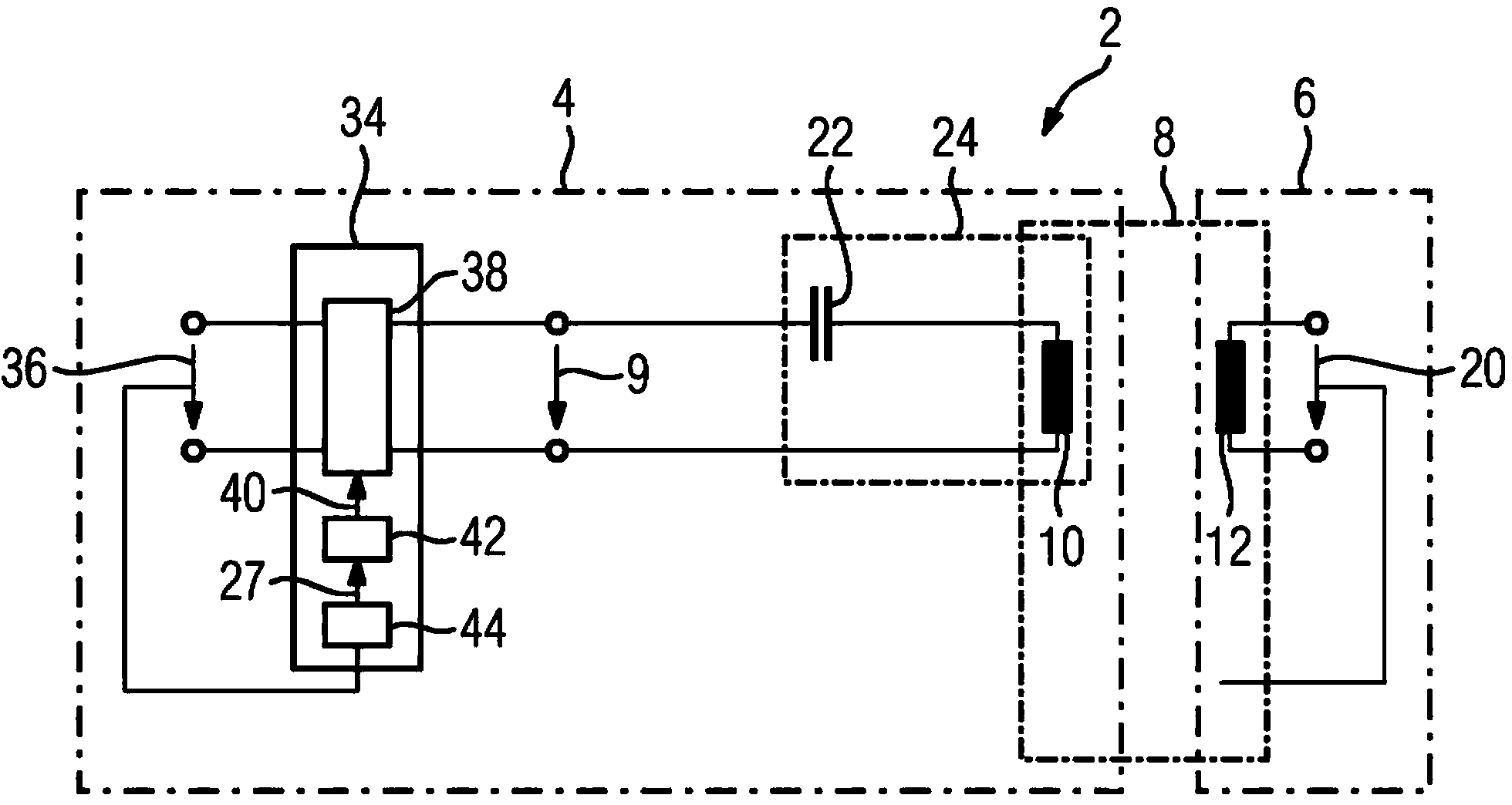
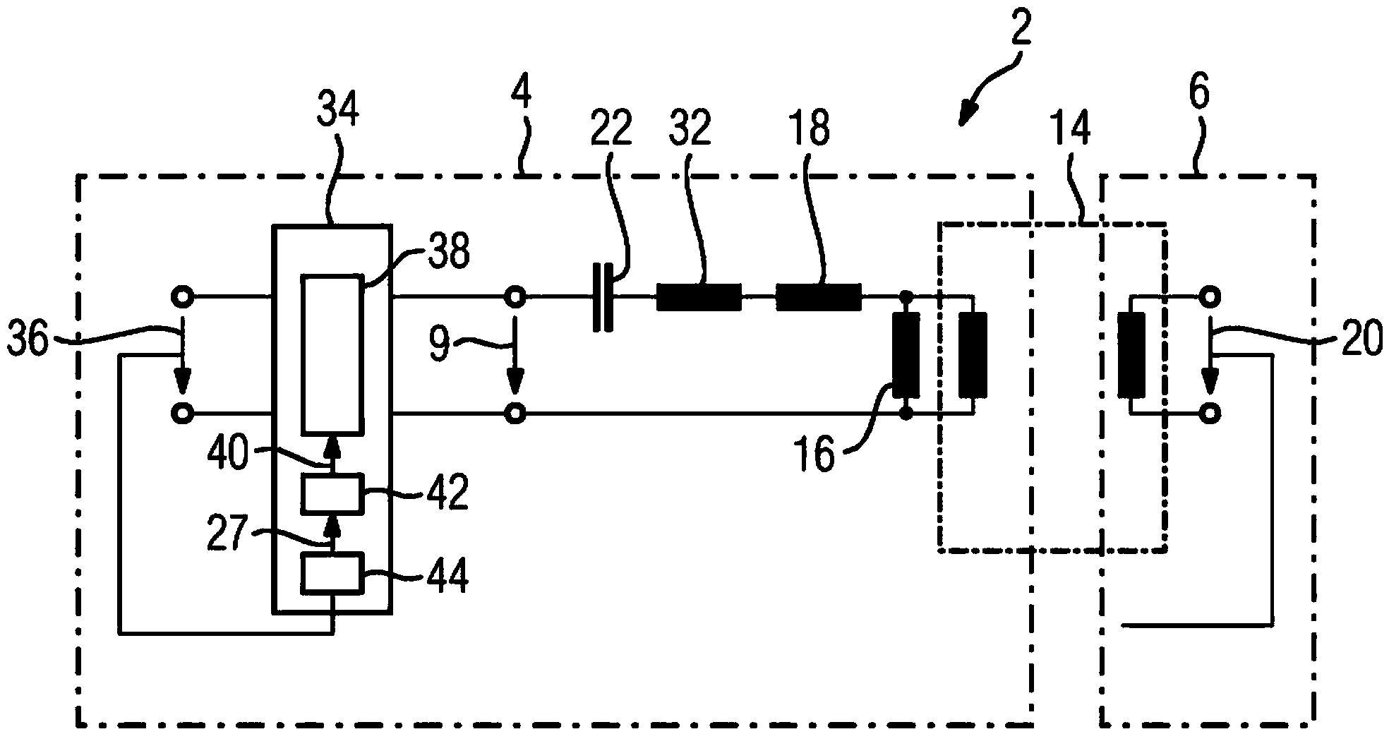
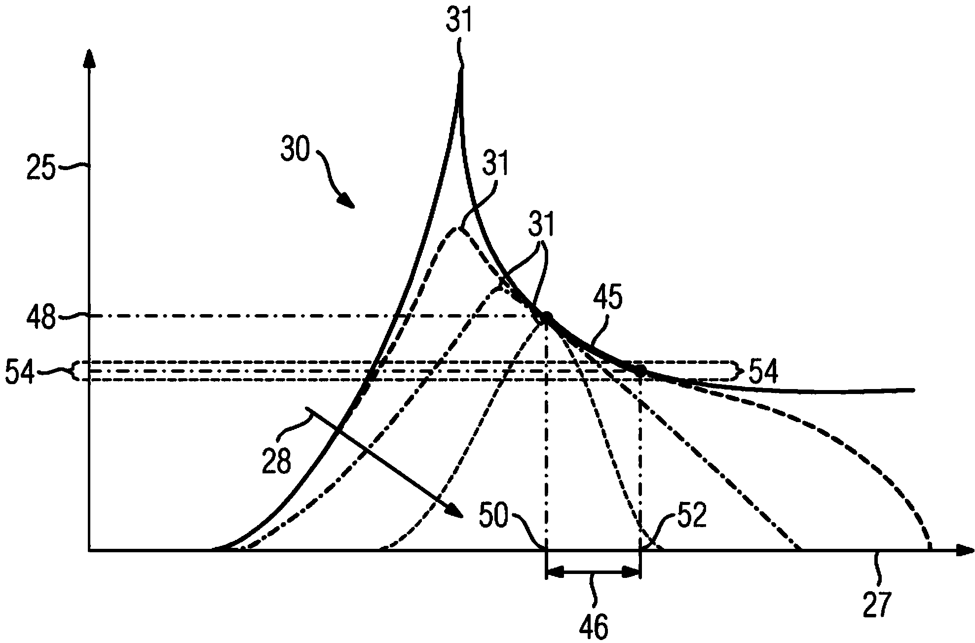
[0043] see Figure 1 to Figure 3 , which correspondingly shows the circuit diagram, equivalent circuit diagram and attenuation diagram of the circuit 2 with supply side 4 and load side 6 . The supply side 4 can be arranged, for example, on a stator of a computer tomograph and the load side 6 can be arranged on an annular tunnel of the computer tomograph.

[0044] In order not to unnecessarily restrict the freedom of movement of the ring tunnel and to limit the material wear of the elements used for the energy transfer from the supply side 4 to the load side 6, the energy transfer takes place wirelessly via a transformer, which figure 1 The actual transformer 8 is shown in . The actual transformer 8 transmits a transmission voltage 9 from a primary winding 10 on the supply side 4 to a secondary winding 12 on the load side 6 .

[0045] as in figure 2 As shown in , the actual transfor...


PUM


Abstract

The invention relates to a circuit for transmitting an input voltage (36) from an electrical energy source (64) in a stator (4, 55) to a load (70) within a device (6) movable relative to the stator (4, 55) comprising an control element (34) for converting an input voltage (36) into a transmission voltage (9), a resonant circuit (24) for receiving the transmission voltage (9), wherein the resonant circuit (24) contains a capacitor (22) and a primary winding (10) of a transformer (8) and the transformer (8) having the primary winding (10) and a secondary winding (12), wherein the primary winding (10) is provided for transmitting the transmission voltage (9) to the secondary winding (12) and the secondary winding (12) is provided for supplying the received transmission voltage (20) to the load (70). According to the invention, the actuator element (34) is provided for detecting the input voltage (36) and adjusting the frequency (27) of the transmission voltage (9) based on a control characteristic (45) in such a manner that the amplitude of the load voltage (20) dropping at the load (70) remains substantially constant, wherein in the control characteristic (45) the transmission ratio (25) of the resonant circuit (24) is plotted over the frequency (27) to be adjusted.

Description

technical field [0001] The invention relates to a circuit according to the preamble of claim 1 , a tomography device, in particular a computed tomography device according to the preamble of claim 26 and a tomography device according to claim 27 method described in the preamble. Background technique [0002] In many electrical appliances there are devices that move relative to the stator, which must be powered from an energy source via the stator. An example for this is a tomography system, such as a computed tomography system, which has an annular tunnel which can accommodate an object whose structure is to be recorded. The ring tunnel is also referred to as a gantry in connection with a computed tomography system. Arranged in the annular tunnel are a plurality of imaging sensors which move along the annular tunnel around the object and thus scan the object. An image of the object structure is generated from the sum of all scan values, which can be output on a screen, for...

Claims


Application Information

Patent Timeline
Patent Type & Authority Applications(China)
IPC IPC(8): H02M3/335H02J5/00
CPCA61B6/56H01F38/14H02J5/005H02M3/33523Y02B70/1433Y02B70/10H02J50/12H02J2310/23H02J50/80
Inventor W.拜尔莱因S.亨克F.霍夫曼
Owner SIEMENS HEALTHCARE GMBH
Why Eureka
Try Eureka