Transformer

A transformer and hollow technology, applied in the field of transformers, can solve the problems of increasing electrical safety, increasing heat dissipation efficiency, insufficient electrical safety distance of transformers, etc.

Inactive Publication Date: 2007-10-24
DELTA ELECTRONICS INC
View PDF0 Cites 3 Cited by
  • Summary
  • Abstract
  • Description
  • Claims
  • Application Information

AI Technical Summary

Problems solved by technology

[0010] The main purpose of the present invention is to provide a transformer, which replaces the secondary side winding coil of the known transformer with a conductive sheet, and the conductive sheet is arranged in the accommodating groove of the separator or the primary winding frame is arranged in the It can not only simplify the assembly process, increase the output power and increase the heat dissipation effect, but also effectively control and increase the leakage inductance, and can also increase the electrical safety, thereby solving the problem of the electrical safety distance of the transformer in the known technology. Insufficient, time-consuming and labor-intensive production, easy deterioration of tape and other problems

Method used


Image

  • Transformer
  • Transformer
  • Transformer

Examples


Embodiment Construction

[0055] Some typical embodiments embodying the features and advantages of the present invention will be described in detail in the description in the following paragraphs. It should be understood that the invention is capable of various changes in different forms without departing from the scope of the invention, and that the description and drawings are illustrative in nature and not limiting of the invention.

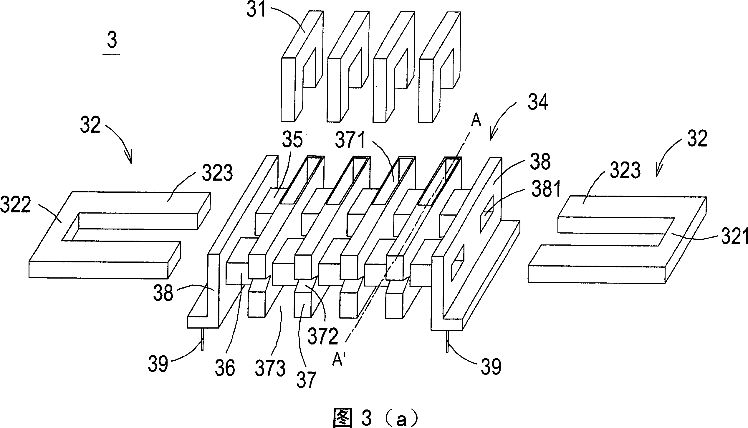
[0056] Please refer to Fig. 3 (a), it is the exploded schematic view of the transformer of the first preferred embodiment of the present invention, as shown in Fig. 3 (a), transformer 3 comprises a plurality of conductive sheets 31, core group 32, primary winding Wire 33 (as shown in FIG. 3( c )) and winding base 34 .

[0057] The winding base 34 is mainly composed of a first hollow plate 35, a second hollow plate 36, a plurality of partitions 37, two side plates 38 and a plurality of pins 39, wherein the first hollow plate 35 and the second Two hollow plates 36 are a...


PUM


Abstract

The related transformer comprises: a primary winding, multiple conductive sheets, a winding base with two hollow plates and some baffle plates, and an iron core assembly, wherein every hollow plate has one throughout path, every baffle plates is set on the first plate and has an accommodation slot for the conductive sheet, and the iron core assembly are set in two paths partially. This invention simplifies assembly process, increases output power and heat dispersion capacity, and improves the electric security.

Description

technical field [0001] The invention relates to a transformer, in particular to a transformer capable of increasing leakage inductance. Background technique [0002] Transformers are electronic components often used in various electrical equipment. Please refer to FIG. 1 , which is a schematic structural diagram of a conventional transformer. As shown in FIG. 1 , the transformer 1 mainly includes an iron core set 11 , a winding base 12 , a primary winding 13 , a secondary winding 14 and the like. Wherein, the primary winding 13 and the secondary winding 14 are wound up and down in the winding area of ​​the winding base 12 , and are insulated and separated from each other by an adhesive tape 15 . The core group 11 can set the axis 111 in the casing 121 of the winding base 12, so that the core group 11, the primary winding 13 and the secondary winding 14 generate electromagnetic coupling induction, so as to achieve the effect of voltage conversion. Purpose. [0003] The co...

Claims


Application Information

Patent Timeline
Patent Type & Authority Applications(China)
IPC IPC(8): H01F27/00H01F27/24H01F27/28
Inventor 张世贸
Owner DELTA ELECTRONICS INC
Why Eureka
Try Eureka