Module for parallel lighting and balancer coil for discharge lamp

a technology of balancer coil and parallel lighting, which is applied in the direction of electric variable regulation, process and machine control, instruments, etc., can solve the problems of unstable effects of balancer coil, inability to realize the small and thin form of balancer coil, and uncertain practical feasibility of cold-cathode florescent lamp use, etc., to increase the self-resonance frequency of each coil, reduce coupling coefficient, and increase leakage inductance

Inactive Publication Date: 2006-03-16
HONG FEI CHEN +2
View PDF11 Cites 2 Cited by
  • Summary
  • Abstract
  • Description
  • Claims
  • Application Information

AI Technical Summary

Benefits of technology

[0065] In order to achieve the above objects, the present invention has been achieved to realize a balancer coil for discharge lamps having two coils whose magnetic fluxes face each other, wherein the magnetic fluxes generated by the coils are canceled by facing, lamp currents of the discharge lamps are balanced by making the sum of reactances of the mutual inductance of the balancer coil larger than the negative resistance of the discharge lamp, and balance effect can be maintained even in a small / flat balancer coil by applying section winding to each coil of the balancer coil so as to make self-resonance frequency of each coil higher.
[0066] It is another object of the present invention, in a shunt circuit module having a balance effect of lamp currents of multiple discharge lamps comprising multiple balancer coils for canceling the pair of magnetic fluxes, wherein the balancer coil has two coils whose magnetic fluxes face each other; one end of either coil of the balancer coil is connected to the other coil of the balancer coil and connected to one end of the electrode of the discharge lamp through the coil so as to mutually connect the multiple the balancer coils circulatingly by repeating this; and one ends of the balancer coil which are not connected to the discharge lamp are integrally connected, the balancer coil suppresses the circulating current flowing between the shunt coils by decreasing coupling coefficient so as to increase leakage inductance; and a magnetic circuit is structured so that the magnetic fluxes generated in the cores of the multiple shunt coils face and cancel each other in all core connection parts.
[0067] It is still another object of the present invention, in the shunt circuit module, to achieve a shunt circuit module wherein the influence of parasitic capacitance is decreased by considering the parasitic capacitance generated in the connecting line connecting respective shunt coils.
[0068] It is still another object of the present invention, in the shunt circuit module, to achieve a shunt circuit module wherein the influence of parasitic capacitance is decreased by alternately connecting the connecting line connecting the respective shunt coils so as to make the lengths of the connecting lines connecting the shunt coils almost equal.
[0069] Furthermore, it is another object of the present invention to improve the shunt / balance effects of a balancer coil near self-resonance frequency by considering the delay of the distributed constant generated in each winding.
[0070] Additionally, it is another object of the present invention to improve the shunt / balance effects of a balancer coil by providing a short-circuit winding wound up adjacent to each winding so as to mutually connect the short-circuit windings.

Problems solved by technology

However, each of the solutions contains an extreme instability, and the practical feasibility for the use of cold-cathode florescent lamps is uncertain.
One of the main reasons is the fact that the effects of a balancer coil are unstable.
Another is the fact that a balancer coil has not been realized to have a small and thin form to meet the market demands even though the coil has stable effects.
For the application of a cold-cathode florescent lamp, however, since the drive voltage and impedance of a cold-cathode florescent lamp are high, the reactance required for a balancer is also large.
In addition, the influence of the parasitic capacitance produced in each high-voltage part or on windings cannot be ignored.
When either of the cold-cathode florescent lamps connected to a balancer coil is not lighted, the core of the balancer coil is saturated, thereby increasing the core loss to elevate temperature.
Those skilled in the art do not necessarily understand correctly the technique of a balancer.
As is seen from Japanese Patent No. 3291852, however, the technical idea persists that coupling coefficient and uniformity in a winding parameter are required as the main parameter showing the effect of a shunt / balance characteristic, and it is the conventional knowledge that there are many restrictions in designing a balancer coil.
It is difficult for the example as disclosed in the publication of Japanese Patent No. 3291852 and many prior arts to have a voltage breakdown structure.
However, it is difficult to say that such finding has been known among those skilled in the art and no such finding has been disclosed in the prior art.
Most of the reasons that a balancer coil for cold-cathode florescent lamps is too unstable for practical use are originated from excessive winding for securing mutual inductance.
Specifically, this is because excessive winding leads to too low self-resonance frequency of the balancer coil, which results in shunt / balance effect has been lost.
Thus, when exceeding the range and when not reaching the range, the shunt / balance effects are lost.
When self-resonance frequency becomes too low, the balancer coil loses shunt / balance effects.
This example, however, severely damages the balance effect.
In this connection method, however, a circulating current flows thereby decreasing the performance unless the leakage inductance of a balancer coil is made large.
Although this method has sufficient shunt / balance effects with three or four lamps, lamps of a number exceeding four decrease each coupling coefficient between windings as the number of lamps increases, thereby decreasing mutual inductance effective for shunting / balancing so that shunt / balance effects are gradually lost.

Method used


Image

  • Module for parallel lighting and balancer coil for discharge lamp
  • Module for parallel lighting and balancer coil for discharge lamp
  • Module for parallel lighting and balancer coil for discharge lamp

Examples


Embodiment Construction

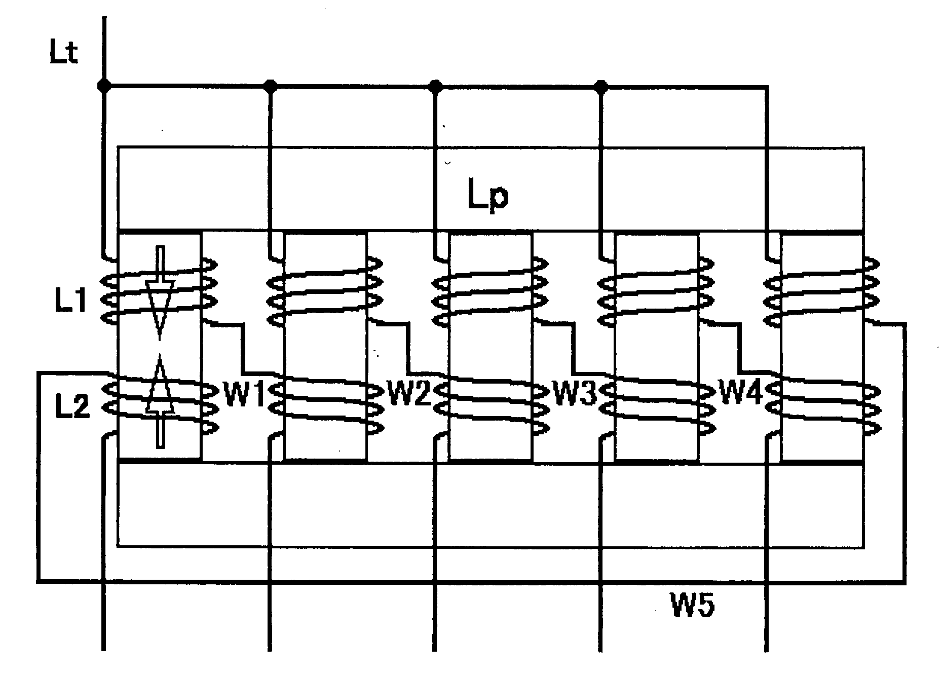
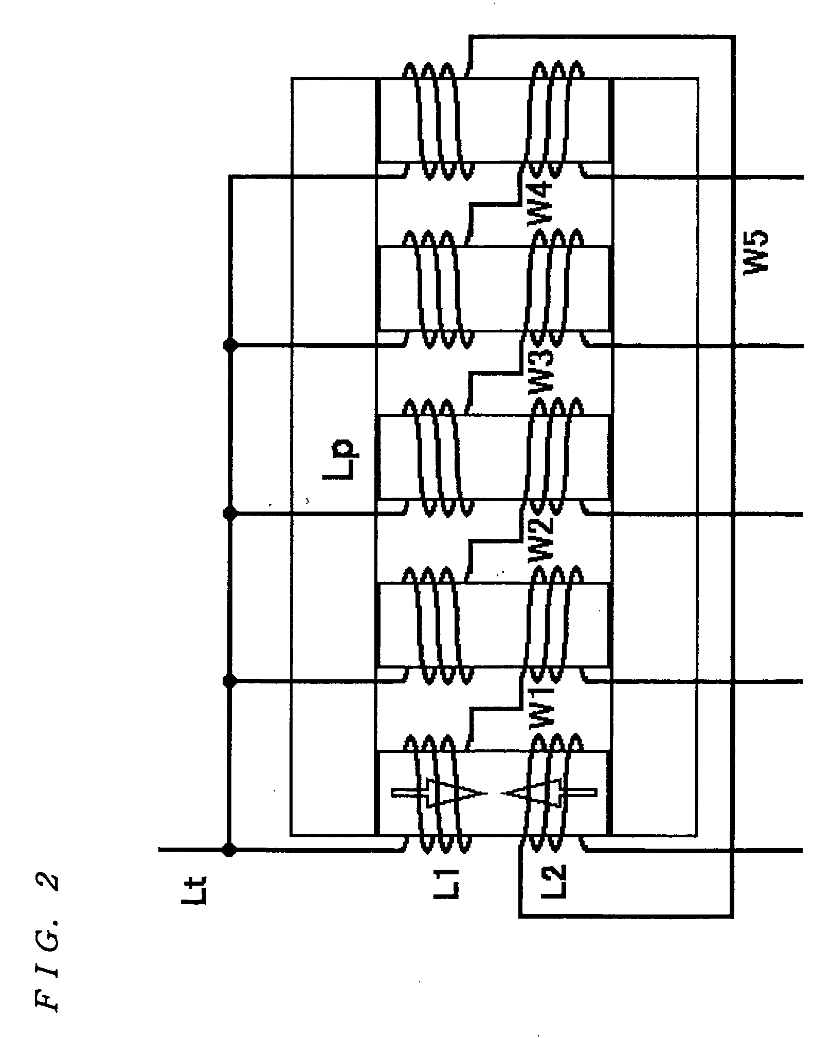
[0104]FIG. 1 shows an embodiment of the present invention, wherein a balancer coil for cold-cathode florescent lamps is designed to make self-resonance frequency of each coil higher by applying section winding to each coil of the balancer coil, as an alternative method for achieving FIG. 21 in the specification of Japanese Patent Application No. 2004-3740 (U.S. Patent Application No. 2004-155596).

[0105] In one embodiment shown in FIG. 1, each coil of the balancer coil has three sections. As a result, when mutual inductance is 600 mH, self-resonance frequency can be 120 kHz. In this case, coupling coefficient does not particularly have to be high, and it is only necessary to secure a required mutual inductance. The balancer coil of this embodiment, therefore, is not limited to a generally rectangular parallelepiped as in the prior art, and can be flat or slim.

[0106] Section structure increases the breakdown voltage of the balancer coil in this embodiment, and this embodiment is app...


PUM


Abstract

A small balancer coil for cold-cathode florescent lamps having sufficient shunt/balance effects, comprises a discharge lamp, a conductor located close to the discharge lamp, and two coils whose magnetic fluxes face each other. The magnetic fluxes generated in the coils face and cancel each other. Lamp currents of the discharge lamps are balanced by making the sum of the reactances of the mutual inductance of the balancer coil larger than the negative resistance of the discharge lamp. Section winding is applied to each coil of the balancer coil so as to maintain shunt and balance effects even in a small/flat balancer coil by making self-resonance frequency of each of the coils higher.

Description

[0001] This application claims priority to Japanese Patent Application Nos. 2004-254129 filed on Sep. 1, 2004, 2004-348380 filed on Dec. 1, 2004 and 2005-117996 filed on Apr. 15, 2005. TECHNICAL FIELD [0002] The present invention is a dependent invention of the invention of Japanese Patent Application No. 2004-3740 (U.S. Patent Application 2004-155596) filed by the inventors of the present invention, and pertains to a module for parallel lighting and a balancer coil for discharge lamps for a liquid crystal display television and a surface light source. BACKGROUND OF THE INVENTION [0003] Although balancer coils are generally used for hot-cathode florescent lamps and known, they were initially intended for low-voltage discharge lamps and were not small-sized. [0004] Since the balancer coil is required to be small for cold-cathode florescent lamps and the drive voltage thereof is high, parasitic capacitance should be taken into consideration, which does not require consideration for ho...

Claims


Application Information

Patent Timeline
Patent Type & Authority Applications(United States)
IPC IPC(8): H05B39/04
CPCY02B20/185H05B41/2822Y02B20/00H01J7/46H01J61/56H05B41/282
Inventor USHIJIMA, MASAKAZU
Owner HONG FEI CHEN
Why Eureka
Try Eureka