Radiation detector and radiographic apparatus

a radiographic apparatus and detector technology, applied in the field of radiographic detectors and radiographic apparatuses, can solve the problems of serious influence of suppress the lowering of the dynamic range dr, so as to reduce the dynamic range, suppress the lowering of the dynamic range, and achieve spatial resolution high

Inactive Publication Date: 2012-06-07
SHIMADZU CORP
View PDF3 Cites 15 Cited by
  • Summary
  • Abstract
  • Description
  • Claims
  • Application Information

AI Technical Summary

Benefits of technology

[0010]This invention has been made having regard to the state of the art noted above, and its object is to provide a radiation detector and a radiographic apparatus which can suppress lowering of a dynamic range when images are acquired with binning.
[0012]According to the radiation detector of this invention, the controller varies the bias voltage applied from the bias supply to the conversion layer based on the presence or absence of binning, that is, for the case of carrying out binning where the switching elements are driven on a basis of a plurality of rows at a time by the gate drive circuit, and for the case of carrying out no binning where the switching elements are driven on a row-by-row basis by the gate drive circuit. Therefore, in the case of a fluoroscopic mode for acquiring images with binning, a lowering of the dynamic range can be suppressed. In the case of a radiographic mode with no binning, the spatial resolution can be made high. That is, with a conventional apparatus, the dynamic range will be reduced when the bias voltage required for the radiographic mode is used as it is for the fluoroscopic mode, and spatial resolution will be reduced when the bias voltage is set low to suit the fluoroscopic mode. However, this invention can secure both high dynamic range and high spatial resolution according to the modes of operation.
[0013]In the above radiation detector, it is preferred that the controller is arranged to set the bias voltage applied from the bias supply to the conversion layer lower for the case of carrying out the binning than for the case without the binning. Consequently, the bias voltage is set lower for the fluoroscopic mode which acquires images by binning 2×2 pixels, for example, than when no binning is carried out, thereby reducing the amount of read-out charges due to leak current for two pixels, to suppress lowering of the dynamic range. The bias voltage is set higher for the radiographic mode which acquires images with no binning, than when binning is carried out, thereby increasing the spatial resolution.
[0014]In the above radiation detector, it is preferred that the larger is the number of rows of the switching elements driven by the gate drive circuit, the lower the controller is arranged to set the bias voltage applied from the bias supply to the conversion layer. In this way, a lowering of the dynamic range can be suppressed according to the number of pixels in the vertical direction to be binned (the number of rows).
[0015]In a preferred example of the above radiation detector, the conversion layer is formed of one of CdTe and CdZnTe. CdTe or CdZnTe is highly sensitive to incident X-rays, and has a large amount of leak current compared with a-Se, for example. Therefore, when binning 2×2 pixels, the dynamic range will lower since the charges due to leak current for two pixels are read. However, by changing the bias voltage, the lowering of the dynamic range can be suppressed.
[0017]According to the radiographic apparatus of this invention, the controller varies the bias voltage applied from the bias supply to the conversion layer based on the presence or absence of binning, that is, for the case of carrying out binning where the switching elements are driven on the basis of a plurality of rows at a time by the gate drive circuit, and for the case of carrying out no binning where the switching elements are driven on the row-by-row basis by the gate drive circuit. Therefore, in the case of a fluoroscopic mode for acquiring images with binning, a lowering of the dynamic range can be suppressed. In the case of a radiographic mode with no binning, the spatial resolution can be made high. That is, with a conventional apparatus, the dynamic range will be reduced when the bias voltage required for the radiographic mode is used as it is for the fluoroscopic mode, and spatial resolution will be reduced when the bias voltage is set low to suit the fluoroscopic mode. However, this invention can secure both high dynamic range and high spatial resolution according to the modes of operation.

Problems solved by technology

This poses a problem of lowering a dynamic range DR.
This results in a serious influence of the lowering of the dynamic range DR.

Method used


Image

  • Radiation detector and radiographic apparatus
  • Radiation detector and radiographic apparatus
  • Radiation detector and radiographic apparatus

Examples


embodiment 1

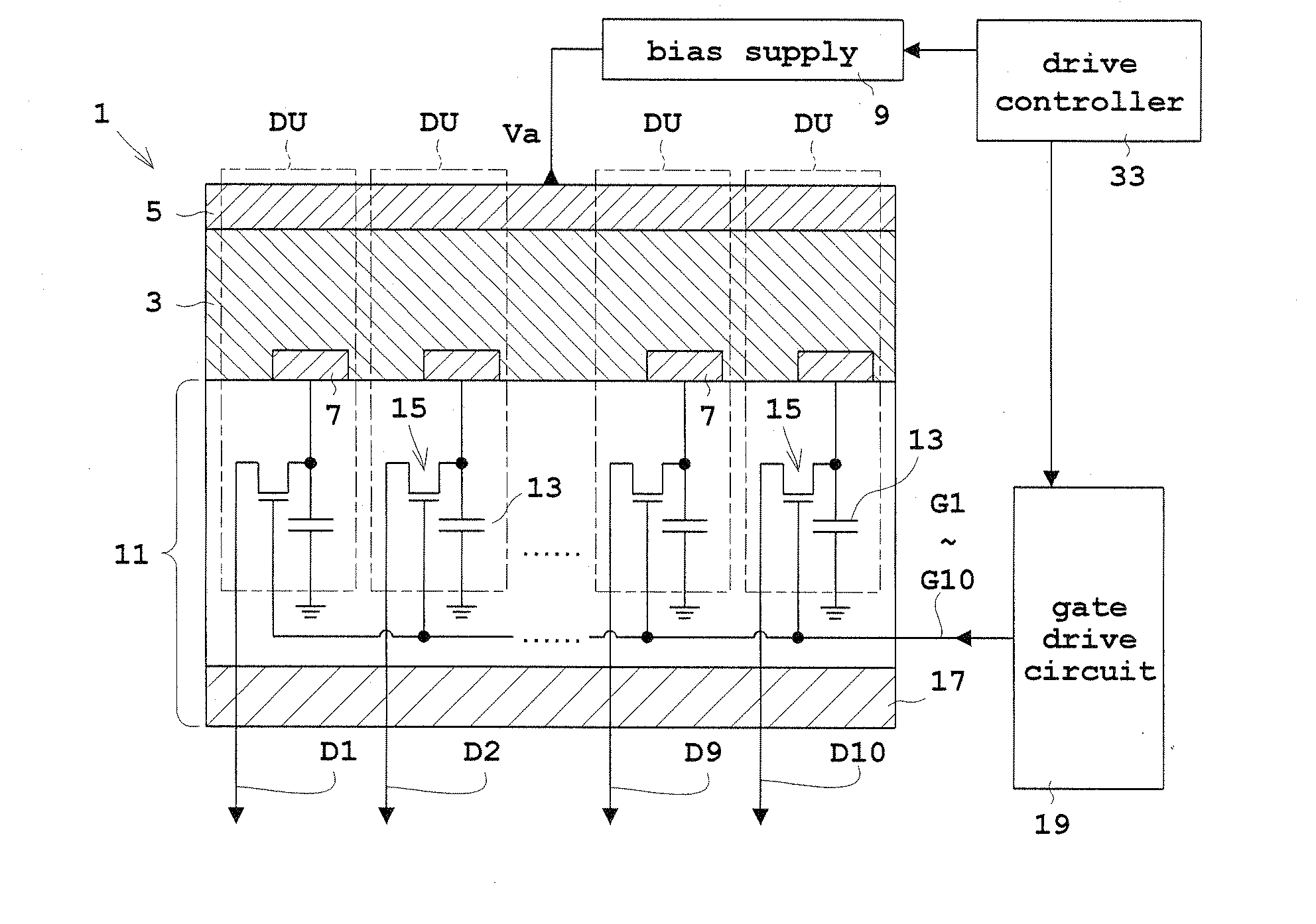
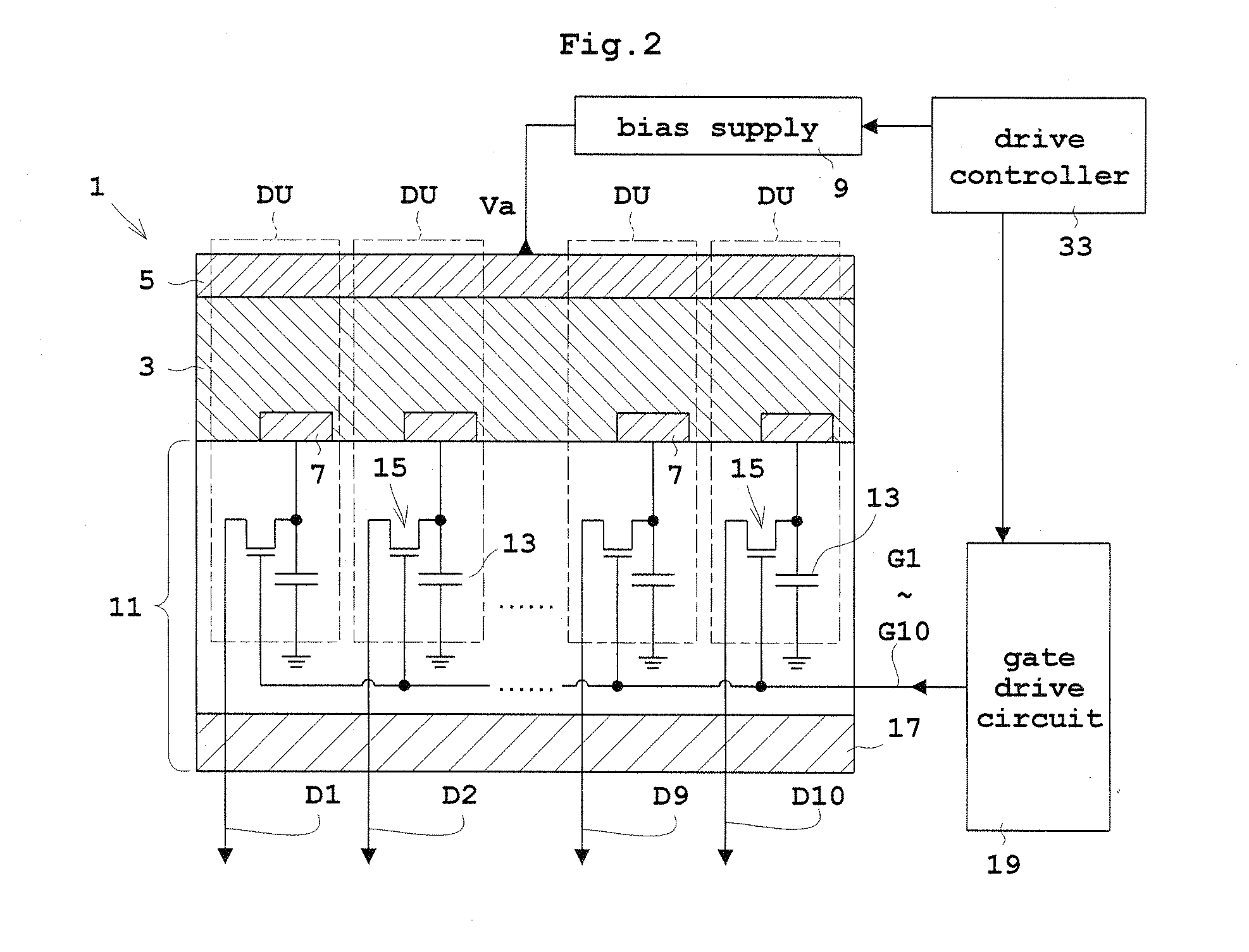
[0031]In the following embodiments, a flat panel X-ray detector will be described as an example of the radiation detector. FIG. 2 is a view in vertical section showing an outline construction of a flat panel X-ray detector according to Embodiment 1. FIG. 3 is a plan view thereof.

[0032]Reference is made to FIGS. 2 and 3. A flat panel X-ray detector (FPD) 1 includes a conversion layer 3 for converting incident X-rays directly into electric charges, a common electrode 5 disposed on one surface of the conversion layer 3 for application of a bias voltage Va, and pixel electrodes 7 arranged opposite the common electrode 5 across the conversion layer 3 for collecting the electric charges converted by the conversion layer 3.

[0033]The conversion layer 3 is formed of a-Se (amorphous selenium), CdTe (cadmium telluride) or CdZnTe (cadmium telluride zinc), for example. When the conversion layer 3 is formed of a-Se, a bias voltage Va of about 10 kV is applied. When the conversion layer 3 is forme...

embodiment 2

[0058]Next, Embodiment 2 of this invention will be described with reference to the drawings. FIG. 6 is a view showing an outline construction of an X-ray apparatus according to Embodiment 2. Components identical to those of the foregoing embodiment will not be described.

[0059]Reference is made to FIG. 6. An X-ray apparatus 41 according to Embodiment 2 includes the FPD 1 of Embodiment 1. Further, the X-ray apparatus 41 includes an X-ray tube 43 for emitting X-rays, an X-ray tube controller 45 for controlling the X-ray tube 43 as required for X-ray emission, and a main controller 47 for performing overall control of the various components of the X-ray apparatus 41.

[0060]The X-ray tube controller 45 has a high voltage generator 49 for generating tube voltage and tube current for the X-ray tube 3. The main controller 47 operates the X-ray tube controller 45, drive controller 33 of the FPD 1, and image processor 31. The X-ray tube 43 corresponds to the radiation emitter in this invention...


PUM

PropertyMeasurementUnit
bias voltageaaaaaaaaaa

Abstract

A drive controller varies a bias voltage applied from a bias supply to a conversion layer based on the presence or absence of binning, that is, for a case of carrying out binning where switching elements are driven on the basis of a plurality of rows at a time by a gate drive circuit, and for a case of carrying out no binning where the switching elements are driven on a row-by-row basis by the gate drive circuit. Therefore, in the case of a fluoroscopic mode for acquiring images with binning, a lowering of a dynamic range can be suppressed. In the case of a radiographic mode with no binning, spatial resolution can be made high. That is, a high dynamic range and high spatial resolution can be optimized according to modes of operation.

Description

BACKGROUND OF THE INVENTION[0001](1) Field of the Invention[0002]This invention relates to a radiation detector and a radiographic apparatus used in the medical field or industrial field for detecting radiation such as X-rays or gamma rays.[0003](2) Description of the Related Art[0004]Conventionally, a flat panel X-ray detector (hereinafter abbreviated as “FPD” as appropriate), for example, is known as this type of radiation detector. The FPD has a construction including, laminated one over the other, a conversion layer which converts X-rays into electric charges (signal charges), and an active matrix substrate for storing and reading the charges converted by the conversion layer.[0005]As shown in FIG. 1, an active matrix substrate 111 has a two-dimensional arrangement of storage capacitors 113 for storing electric charges converted by a conversion layer 103, and switching elements 115 for reading the electric charges stored in the storage capacitors 113. Gate (address) lines G1-G10...

Claims


Application Information

Patent Timeline
Patent Type & Authority Applications(United States)
IPC IPC(8): G01T1/24G01N23/04
CPCG01T1/247H04N5/378H04N5/347H04N5/32H04N25/46H04N25/75
Inventor YOSHIMATSU, AKINATANABE, KOICHITOKUDA, SATOSHIYOSHIMUTA, TOSHINORIKISHIHARA, HIROYUKIKAINO, MASATOMOSATO, TOSHIYUKIKUWABARA, SHOJI
Owner SHIMADZU CORP
Why Eureka
Try Eureka