Field-emission electron gun and method for controlling same

a field-emission electron gun and field-emission technology, applied in the direction of cathode ray tubes/electron beam tubes, electric discharge tubes, electrical equipment, etc., can solve the problems of cathode being destroyed, cathode surface rough, and prone to unstable emission current, so as to make the most of the original high brightness of the w field-emission electron source.

Active Publication Date: 2013-08-08
HITACHI HIGH-TECH CORP
View PDF4 Cites 14 Cited by
  • Summary
  • Abstract
  • Description
  • Claims
  • Application Information

AI Technical Summary

Benefits of technology

[0012]According to the present invention, it is possible to make the most of the ori

Problems solved by technology

On the other hand, since it operates at the room temperature, the emission current is apt to become unstable due to gas adsorption.
There is a possibility that

Method used


Image

  • Field-emission electron gun and method for controlling same
  • Field-emission electron gun and method for controlling same
  • Field-emission electron gun and method for controlling same

Examples


embodiment 1

[0043]As for the timing of the flashing, an ammeter for measuring the actual Ip is provided, timing (τ90) when Ip has reached 90% of the initial value which is time when Ip decreases rapidly is monitored, and a controlling unit controls flashing at that time point.

[0044]On the other hand, in the case where gas molecules other than hydrogen remain on the surface of the electron source, or in the case where a peripheral electrode such as the anode is contaminated, it is more desirable to use a different scheme in some cases.

[0045]In the case where the W field-emission electron source is used as the electron source of an electron microscope, a high brightness image observation can always be conducted by conducting the flashing in accordance with τf, where τf is time when rapid decrease of the probe current Ip begins (in FIG. 4, which is a boundary between stable areas (the areas I and II) and an decrease area (the area III)). Usually, τf is close to τ90. Depending upon the surface stat...

embodiment 2

[0049]Pressure around the electron source will now be described.

[0050]For prolonging the high brightness observation time by at least several hours, degasing by heating components in a vacuum furnace having a pressure of the 10−3 Pa level or less and 400° C. or above and electrolytic polishing are executed, a W single crystal field-emission electron source is mounted on an electron gun with a gas emission amount reduced in this way, and the pressure around the electron source is kept at the 10−9 Pa level or less by using an exhausting system capable of lowering the pressure to the 10−9 Pa level or less.

embodiment 3

[0051]Hereafter, a concrete form for implementing the present invention described above will be described in detail with reference to the drawings.

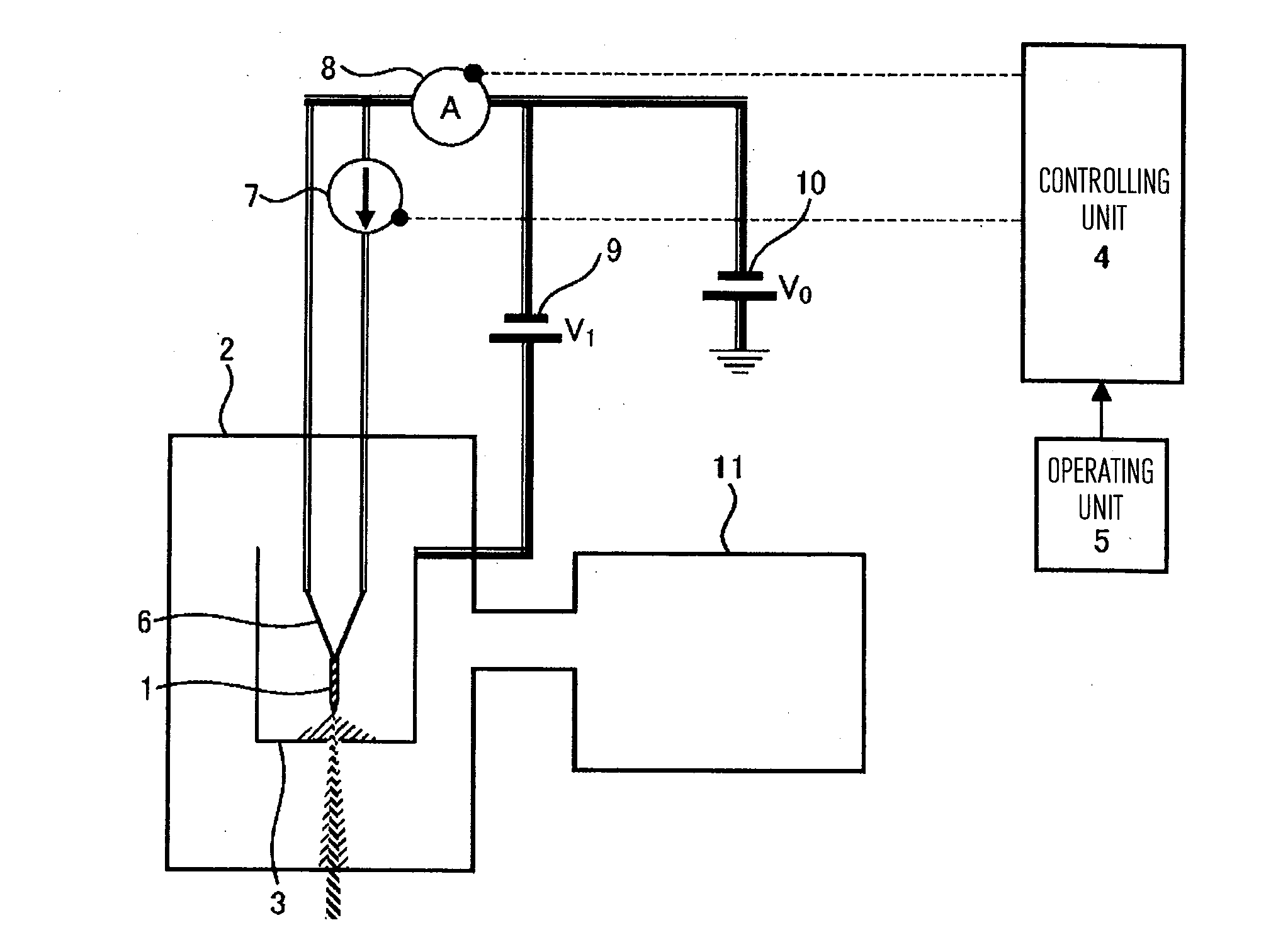
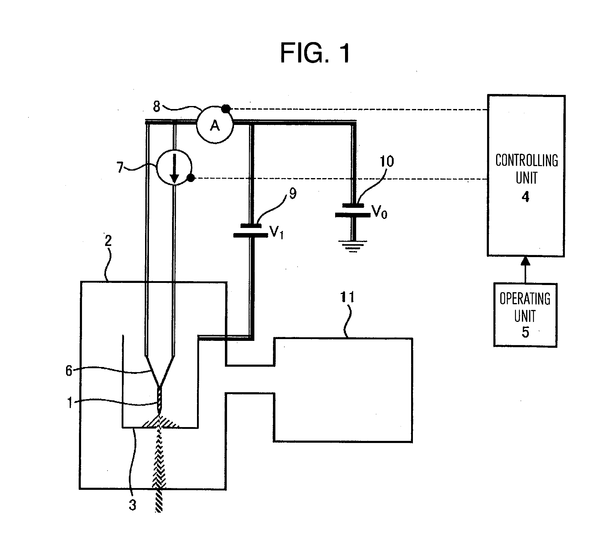
[0052]FIG. 1 is a schematic diagram showing a configuration of an ultra-high vacuum electron gun and its control system according to an embodiment of the present invention. In the present embodiment, the ultra-high vacuum electron gun includes a W field-emission electron source 1 using a (310) oriented single crystal W tip and a vacuum chamber 2 of ultra-high vacuum. The pressure in an electron gun chamber in the vacuum chamber 2 of ultra-high vacuum is kept at ultra-high vacuum of the 10−9 Pa level or less. By the way, the present embodiment uses the aspect of the invention in the embodiment 1 and the aspect of the invention in the embodiment 2 jointly. However, it is also possible to use either one of the aspects of the inventions.

[0053]In FIG. 1, the ultra-high vacuum electron gun includes a vacuum chamber 2 of ultra-high vacuum having...


PUM


Abstract

The disclosed charged particle beam apparatus includes a field-emission electron source including <310> single crystal of tungsten; a vacuum chamber having the electron source therein; an exhausting system for exhausting the vacuum chamber; a filament connected to the electron source to let flow a current through the electron source and thereby heat the electron source; a power supply for letting a current flow through the filament; an ammeter for measuring a total current emitted from the electron source; and a controlling unit for exercising control to cause the power supply to let a current flow through the filament when the total current measured periodically has become a predetermined ratio or less as compared with a total current from the electron source found immediately after first electron beam emission, or a total current from the electron beam found immediately after a current is let flow through the filament.

Description

TECHNICAL FIELD[0001]The present invention relates to a field-emission electron gun and a method for controlling it, and in particular to an electron gun mounting a W<310> field-emission electron gun and a method for controlling it.BACKGROUND ART[0002]If a strong electric field is applied to a metal surface, a potential barrier has an inclination at a boundary to vacuum. If the electric field becomes at least 107 V / cm, the barrier becomes superfine-pointed and electrons are emitted into the vacuum. This is called field emission. Dispersion of energy of emitted electrons becomes small and it is approximately 0.3 eV. An apex of a field-emission electron source is finished to have a radius of curvature of approximately 100 nm in order to generate a strong electric field.[0003]Since the size of the spot diameter of the field-emission electron gun is as small as 5 to 10 nm, the field-emission electron gun has a feature that the brightness is extremely high and it is used often as a...

Claims


Application Information

Patent Timeline
IPC IPC(8): H01J29/98
CPCH01J37/073H01J2237/022H01J29/98H01J2237/1825H01J2237/0653
Inventor CHO, BOKLAEKOKUBO, SHIGERUMURAKOSHI, HISAYANITTA, HISAO
Owner HITACHI HIGH-TECH CORP
Why Eureka
Try Eureka