Artificial hip joint femur-end artificial body

A technology for hip joints and femurs, applied in the direction of hip joints, femoral heads, joint implants, etc., can solve the problems that the effectiveness of clinical application is not confirmed, the reliability of prosthesis fixation and long-term stability have not been confirmed, etc. , to achieve the effect of preventing prosthesis from moving inward, reducing bone loss and improving stability

Inactive Publication Date: 2007-08-29
冀原
View PDF0 Cites 2 Cited by
  • Summary
  • Abstract
  • Description
  • Claims
  • Application Information

AI Technical Summary

Problems solved by technology

[0004] Although the design of the sessile prosthesis conforms to the biomechanical characteristics of the femur, the effectiveness of clinical application is not sure, because the reliability and long-term stability of the prosthesis have not been confirmed.

Method used


Image

  • Artificial hip joint femur-end artificial body
  • Artificial hip joint femur-end artificial body

Examples


Embodiment Construction

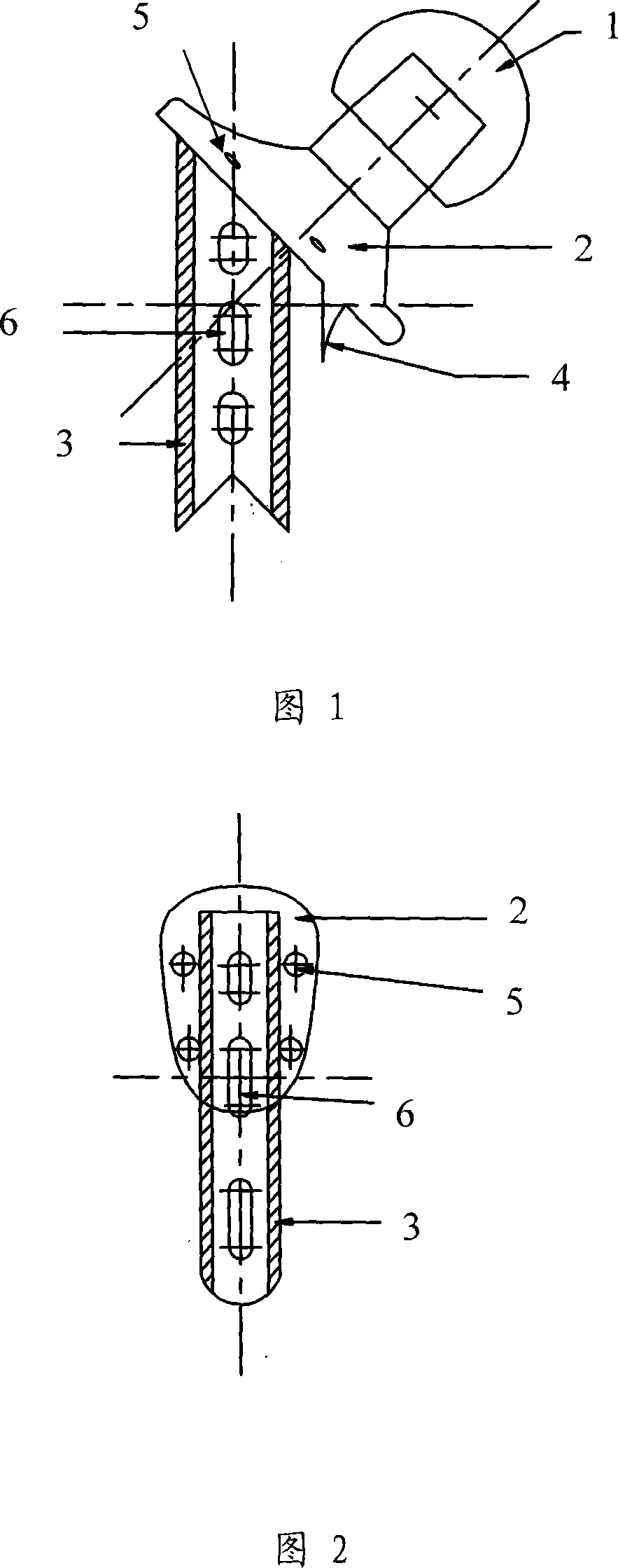
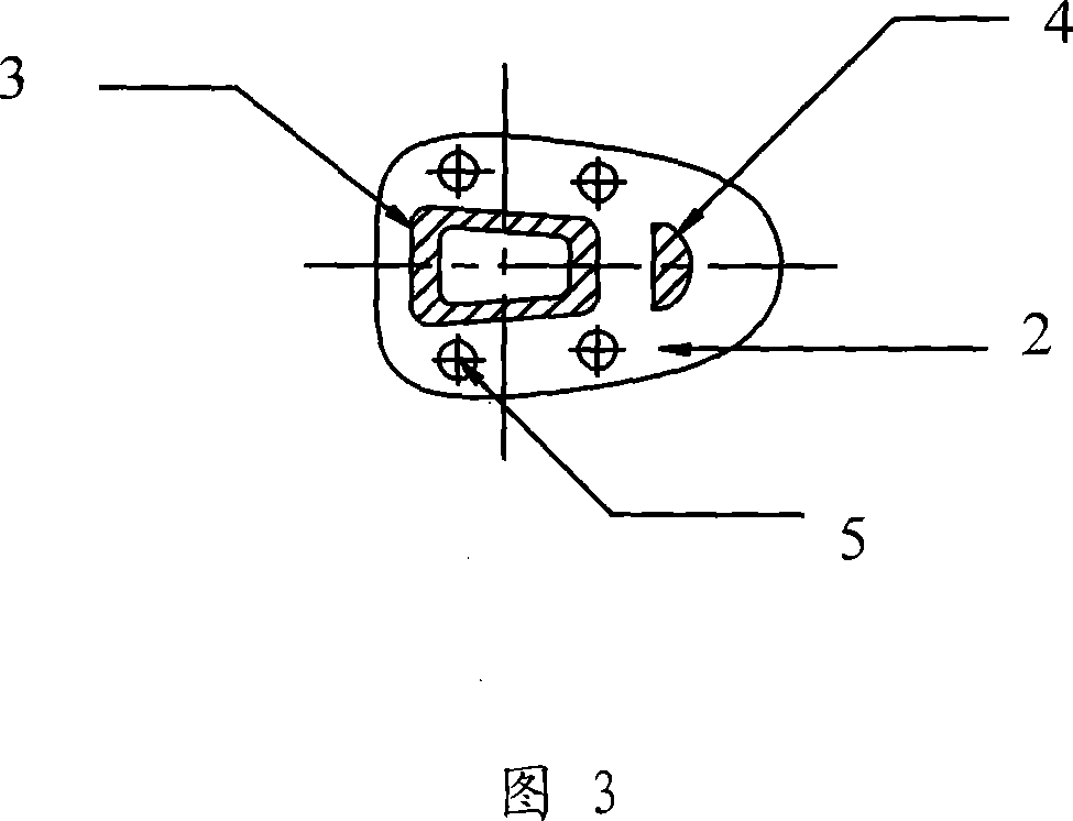
[0015] The artificial hip joint femoral end prosthesis provided by the present invention will be described in detail below with reference to the accompanying drawings and specific embodiments. As shown in Figures 1 to 3, the femoral end prosthesis of the artificial hip joint provided by the present invention includes a head ball 1, a full neck of the femoral neck 2, a hollow half handle of the femoral medullary cavity 3 and a short handle 4 inside the femoral neck; wherein the head ball 1 It is installed on the upper end of the femoral neck full collar 2 in a tightly fitting manner; the two sides of the lower part of the femoral neck full collar 2 are penetrated to form a plurality of full collar fixing holes 5; It is connected to the outer middle of the bottom surface of the femoral neck full collar 2, and the angle between its main body and the femoral neck full collar 2 bottom surface is an acute angle; while the femoral neck medial short stem 4 is spaced apart from the femo...


PUM


Abstract

The present invention discloses a kind of artificial hip-joint femur end prosthesis. It includes the following several portions: head ball, femoral neck whole body, femoral marrow cavity hollow half-stalk and femoral neck inner side short stalk. Said invention also provides the mounting mode of above-mentioned every portion and connection mode of all the above-mentioned portions.

Description

technical field [0001] The invention belongs to the field of medical instruments, in particular to an artificial hip joint femoral end prosthesis for hip joint replacement. Background technique [0002] At present, the femoral end prosthesis of the artificial hip joint clinically used is mainly divided into two types, one is a stem prosthesis, and the other is a sessile prosthesis. [0003] Stemmed prostheses are divided into collared prostheses and collarless prostheses. Among them, the collar of the collared prosthesis is limited to the medial femoral calcar. The advantage is that the prosthetic collar can maintain the original biomechanical characteristics of the medial femur and reduce bone loss. There is a certain influence on the force of the stem, which is likely to cause loosening of the prosthesis; the collarless prosthesis uses the extrusion force of the stem to increase the friction between the stem and the medial femoral cortex, so as to achieve the purpose of s...

Claims


Application Information

Patent Timeline
IPC IPC(8): A61F2/36
Inventor 冀原
Owner 冀原
Why Eureka
Try Eureka