Adjusting device

A technology of regulating device and regulating valve, applied in fuel injection device, charging system, machine/engine, etc., can solve problems such as engine damage, spring breakage, component breakage, etc.

Inactive Publication Date: 2007-08-29
DENSO CORP
View PDF1 Cites 9 Cited by
  • Summary
  • Abstract
  • Description
  • Claims
  • Application Information

AI Technical Summary

Problems solved by technology

As a result, the charge pump 3 may be damaged abnormally, or elements of the charge pump 3 may break to cause damage to the vehicle
Or, the spring of the electroma...

Method used


Image

  • Adjusting device
  • Adjusting device
  • Adjusting device

Examples


no. 1 example

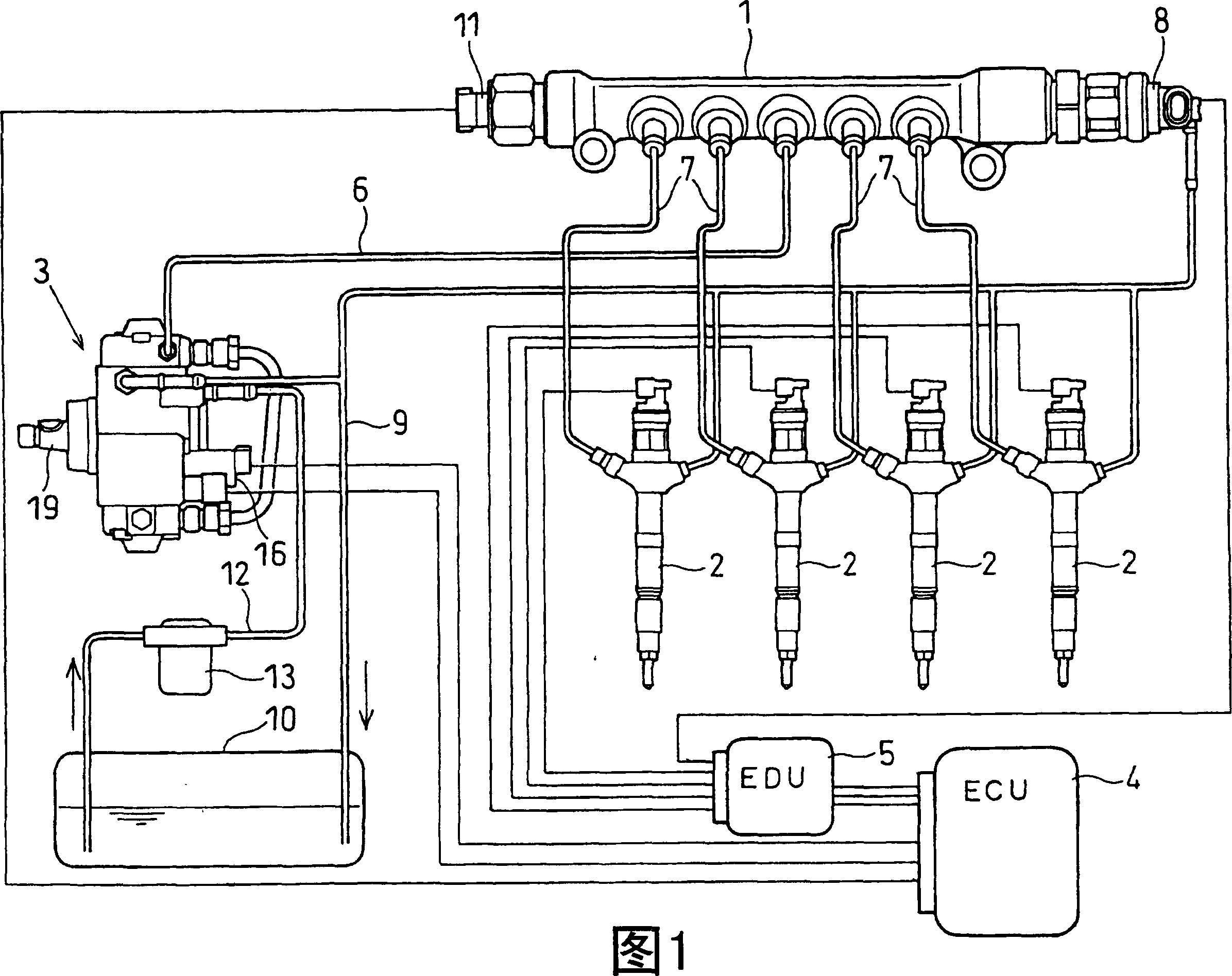
[0019] The common rail type injection system shown in FIG. 1 injects fuel into each cylinder of an engine such as a diesel engine (not shown). The fuel injection system includes a common rail 1, injectors 2, a supply pump 3, an engine control unit (ECU) 4, an electronic drive unit (EDU) 5, and the like. EDU5 may be provided in the housing of ECU4.

[0020] The common rail 1 constitutes a storage container in which high-pressure fuel to be supplied to the injector 2 is stored. The common rail 1 is connected to the discharge port of the supply pump 3 through a high-pressure pump pipe 6 for pressure-feeding high-pressure fuel. Accumulated pressure in common rail 1 (common rail pressure). This common rail pressure corresponds to fuel injection pressure. The common rail 1 is connected to a plurality of injector pipes 7 through which high-pressure fuel is supplied to the respective injectors 2 .

[0021] The pressure regulating valve 8 is also used as a pressure limiter (pressur...

no. 2 example

[0064] As shown in FIG. 5 , the cover 59 includes a bottom in which a through hole 59 a is defined for communicating the inside and outside of the cover 59 . Similar to the first embodiment, when the plug 46 is moved in the outward direction, the plug 46 abuts against the bottom surface of the cover 59 without moving outside the cover 59 .

[0065] The through hole 59 a is arranged substantially coaxially with respect to the plug 46 . When the plug 46 moves outward relative to the valve housing 44, the engine may stop. In this state, by inserting a rod or the like into the through hole 59a to push the plug 46 into the valve housing 44, the engine can be temporarily operated. Therefore, in this embodiment, the plug 46 can be pushed back from the outside, so that the vehicle can stably perform the reverse operation.

no. 3 example

[0067] As shown in FIG. 6 , a cover 59 is fitted onto the valve housing 44 . The cover 59 is generally cup-shaped to be fitted onto the periphery of the tool fitting portion 57 . As shown in Fig. 6(a), the tool engaging portion 57 is generally elliptical to define parallel surfaces 57a, which are opposed to each other when viewed axially. The elliptical tips of the tool fitting portion 57 in the left and right sides of FIG. 6( a ) define an R portion (fitting head).

[0068] The cover 59 is formed of a soft material having a higher modulus of elasticity than the valve housing 44 so that the cover 59 is elastically deformable. Cover 59 may be formed from a thin metal sheet in a generally cup shape. A cover 59 is attached to the periphery of the tool fitting portion 57 . The cover 59 is formed by pressing, for example, stainless steel or the like. When the cover 59 is mounted on the tool fitting portion 57 , the cover 59 is pushed onto the tool fitting portion 57 to be elast...


PUM


Abstract

A regulating device includes a regulating valve with a valve housing, which has a fluid inlet, a fluid outlet, accomodates the valve elements pressing by the fluid pressure in the fluid inlet, biasing element, and is compressed between the valve element and plug, and resists the bias force of the fluid pressure to the valve element. With the development of the fluid pressure, the valve element moves owing to resisting bias force so as to communicate fluid inlet and fluid outlet. The valve element makes the plug move outward relative to the valve housing by bias element so as to reduce the bias force, when the fluid pressure is equal to or more than the preset pressure. A displacement regulation unit coming against plug is to limit its movement and regulate the reduction of the bias force.

Description

technical field [0001] The invention relates to an adjustment device. Background technique [0002] The regulating device includes a regulating valve for controlling the fluid pressure at a predetermined pressure, for example, in JP-A-2002-250459, a regulating device is provided in a supply pump for a common rail type injection system. [0003] As shown in FIG. 8 , the supply pump 3 includes a feed pump 14 , a regulating valve 15 , an electromagnetic metering valve 16 , and a high-pressure pump 17 . A feed pump 14 pressure-feeds fuel from a fuel tank to a high-pressure pump 17 . The regulator valve 17 includes a valve housing 44 having a fluid inlet 41 and a fluid outlet 42 . The regulator valve 15 also includes a valve element 45 , which is movably supported in the valve housing 44 , and a return spring 47 which biases the valve element 45 in a direction to block the fluid inlet 41 . As the pressure of the fluid inlet 41 becomes higher, the regulating valve 15 communicat...

Claims


Application Information

Patent Timeline
IPC IPC(8): F02M59/34F02M51/02
Inventor 羽生俊治
Owner DENSO CORP
Why Eureka
Try Eureka