
Self-conglutinating elastomer layer in solid insulative switch pole

A solid insulation, switching pole technology, applied in electrical switches, high-voltage/high-current switches, high-voltage air circuit breakers, etc., can solve the problems of leakage current, air entry, partial discharge, etc., and achieve the effect of reducing manufacturing costs

Active Publication Date: 2007-08-29
SIEMENS AG
View PDF2 Cites 1 Cited by
  • Summary
  • Abstract
  • Description
  • Claims
  • Application Information

AI Technical Summary

Problems solved by technology

[0004] The previously known solid-insulated switching poles have the disadvantage that air ingress can occur despite the elastic gasket
Risk of leakage currents or partial discharges due to the resulting voltage peaks, especially at higher voltages

Method used


Image

  • Self-conglutinating elastomer layer in solid insulative switch pole

Examples


Embodiment Construction

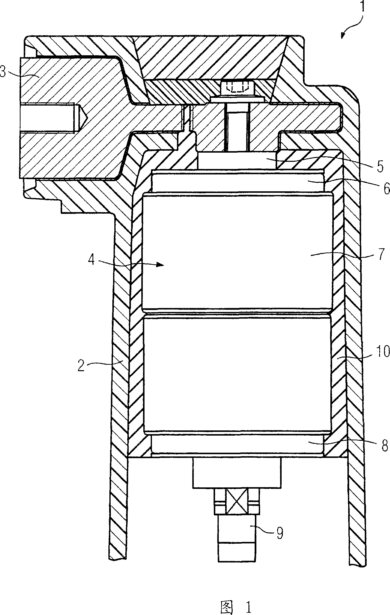
[0018] The drawing shows an exemplary embodiment of a solid-insulated switching pole 1 according to the invention in a cross-sectional view. The solid-insulated switching pole 1 is intended to interrupt the current in one phase of a three-phase network. Since a typical three-phase network has three phases, three solid-insulated switch poles 1 arranged side by side and connected to a common drive unit are usually provided on commercially available switches.

[0019] The illustrated solid-insulated switching pole 1 has an insulating material housing 2 molded from epoxy resin or in other words cast resin, in which an upper connection part 3 and an intermediate connection part, not shown in the diagram, are fastened. Furthermore, a vacuum interrupter 4 can be seen in the insulating material housing 2 , which is rigidly connected to the connection part 3 via a fixed stem 5 . The fixed contact rod 5 clamps against an end shield 6 made of copper, which at the same time carries a sta...


PUM

PropertyMeasurementUnit
Compressive strengthaaaaaaaaaa

Abstract

The aim of the invention is to provide a circuit-breaker pole (1), which is insulated by solid material, with an electrically non-conductive and dimensionally stabile insulating material housing (2), inside of which a switching tube (4) is arranged, this switching tube having a fixed contact as well as a moving contact, which is located opposite the fixed contact on the drive side and which is displaceably guided in a longitudinal manner, the insulating material housing (2) being open on the drive side in order to enable the introduction of a drive movement into the moving contact, and an elastic padding (10), which is easy to produce, is placed between the switching tube (4) and the insulating material housing (2) whereby preventing the trapping of air. To this end, the invention provides that the elastic padding (10) has inherent adhesion properties, and a surface bond both with the switching tube (4) as well as with the insulating material housing (2) is provided, this surface bond being able to be released only by abrasion.

Description

technical field [0001] The invention relates to a solid-insulated switching pole, which has a non-conductive and dimensionally stable insulating housing, in which a pole with a fixed contact and a guide, which is opposite the fixed contact on the drive side and moves in the longitudinal direction, is arranged. The switching tube of the moving contact, wherein the insulating housing is open on the driving side, so that the driving movement can be introduced on the moving contact, and at the same time an elastic gasket is arranged between the switching tube and the insulating housing. Background technique [0002] Such a switching pole is known from patent document EP0866481A2. The switching pole disclosed here has a rigid or otherwise dimensionally stable insulating housing in which a vacuum interrupter is fastened. The vacuum tube has a fixed fixed contact, which is fixedly connected to a connecting piece leading out of the insulating housing. Opposite the stationary conta...

Claims


Application Information

Patent Timeline
IPC IPC(8): H01H33/66
CPCH01H2033/6623H01H33/66207H01H33/664
Inventor 拉尔夫-赖纳·沃尔克马
Owner SIEMENS AG
Learn More