Scattered radiation correction method of computerized tomography system and computerized tomography system

A technology of tomography and computer, which is applied in radiation measurement, computer tomography scanner, and equipment for radiological diagnosis, etc. It can solve problems such as inability to minimize ray scattering, defective shooting results, and gaps in data acquisition.

Inactive Publication Date: 2007-09-05
SIEMENS AG
View PDF1 Cites 23 Cited by
  • Summary
  • Abstract
  • Description
  • Claims
  • Application Information

AI Technical Summary

Problems solved by technology

However, such a scatter etalon cannot minimize the scattering of rays of the same spatial direction produced by other focal points arranged with an angular offset, which have actually straight rays originating from the focal point arranged relative to the detector, while these rays The strength of the should be measured
In principle, therefore, there is the problem of determining this scatter component at the overall measured radiation intensity and correcting this component for the measured radiation intensity, wh...

Method used


Image

  • Scattered radiation correction method of computerized tomography system and computerized tomography system
  • Scattered radiation correction method of computerized tomography system and computerized tomography system
  • Scattered radiation correction method of computerized tomography system and computerized tomography system

Examples


Embodiment Construction

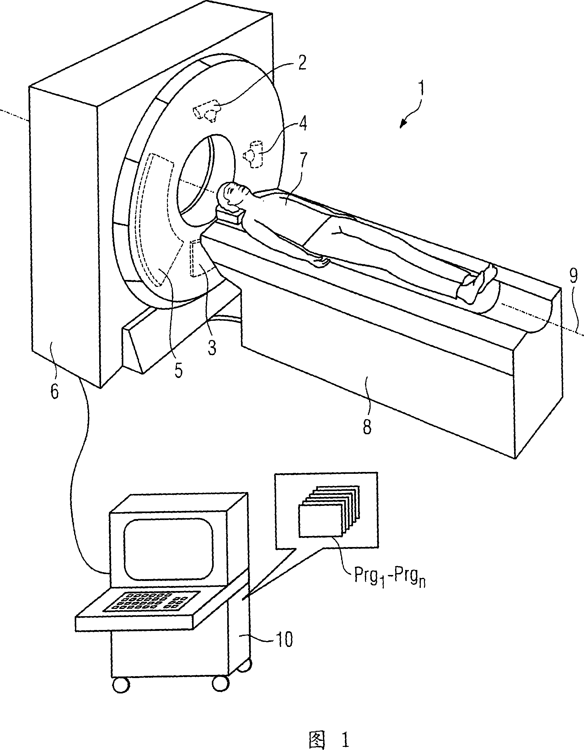
[0044] 1 shows an example of a computed tomography system 1 according to the invention with two focus / detector systems, wherein the first focus / detector system FDSA has an X-ray tube 2 and a detector 3 arranged opposite it, the second The focus / detector system FDSB has an x-ray tube 4 and a detector 5 arranged opposite it. The focus / detector systems 2, 3 and 4, 5 are arranged at an angular offset of 90° relative to each other on a not explicitly shown support in the support housing 6 and move about the system axis 9 during scanning of the patient, while the patient 7 are then moved continuously or sequentially through the scanning area. A longitudinally movable patient couch 8 is used for this purpose, which is controlled by a control and computing unit 10 . The control and computing unit 10 is also responsible for controlling the operation of the stand with the two focus / detector systems 2 , 3 and 4 , 5 . Furthermore, the absorption data acquired by the two focus / detector s...


PUM


Abstract

The present invention relates to a method for scattered radiation correction of a CT system, including at least two focus/detector systems operated angularly offset from one another, is disclosed. In the method, at at least one phantom, similar to the examined object at least in a subregion, for at least one of the focus/detector systems, the scattered radiation intensity occurring is determined in the detector of a focus/detector system during the operation of the at least one focus of at least one other focus/detector system. Further, the spatial distribution thereof is stored for a number of angles of rotation of the focus/detector systems. During scanning of the object, the scattered radiation intensities, determined with the aid of a similar phantom that originate from the at least one other focus/detector system, are subtracted from the measured intensities of the first focus/detector system while taking account of the spatial orientation of the focus/detector systems and the beam respectively considered. Finally, absorption values are calculated with the aid of the intensity values thus corrected, and CT pictures or CT volume data are thereby reconstructed.

Description

technical field [0001] The invention relates to a method for scatter correction of a computed tomography system having at least two focal point / detector systems mounted on a rotatable support angularly offset from one another and operating simultaneously, wherein in order to detect objects Scanning is carried out, the focus / detector system arranged at an angular offset scans the object, wherein they rotate around the system axis of the CT system, and for a plurality of individual rays S according to the measured radiation intensity I and the measured radiation intensity I Attenuated ray intensity I 0 The relationship to determine the absorption value a = -ln (I / I 0 ), and reconstruct the CT image or CT volume data of the object with the aid of the determined absorption data. Background technique [0002] It is known in principle that in CT methods scattering effects occur which lead to inaccurate measurements of the absorption of x-rays. This effect was first observed her...

Claims


Application Information

Patent Timeline
IPC IPC(8): A61B6/03A61B6/00G01T1/161
CPCG03B42/02A61B6/583A61B6/032A61B6/5282A61B6/4014
Inventor 赫伯特·布鲁德马丁·彼得西尔卡雷纳·劳佩克卡尔·施蒂尔斯托弗
Owner SIEMENS AG
Why Eureka
Try Eureka