

Lift-pipe reactor
A reactor and riser technology, applied in the field of riser reactors, can solve the problems that the second reaction zone is difficult to achieve the catalyst density, and the process advantages cannot be fully utilized, so as to increase the catalyst density, increase the catalyst concentration, and circulate The effect of increased strength
- Summary
- Abstract
- Description
- Claims
- Application Information
AI Technical Summary
Problems solved by technology
Method used
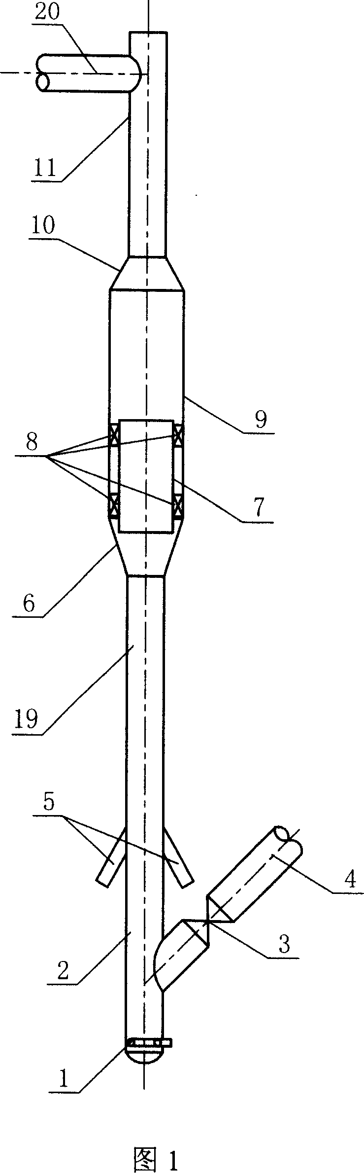
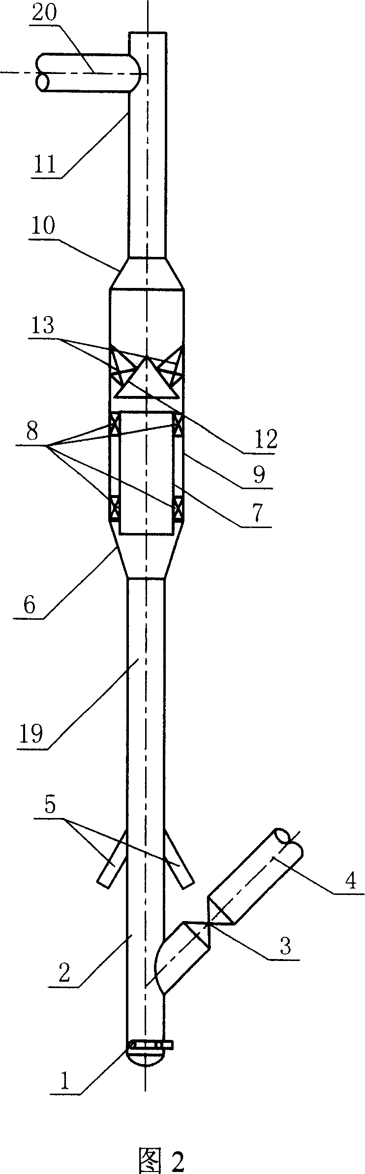
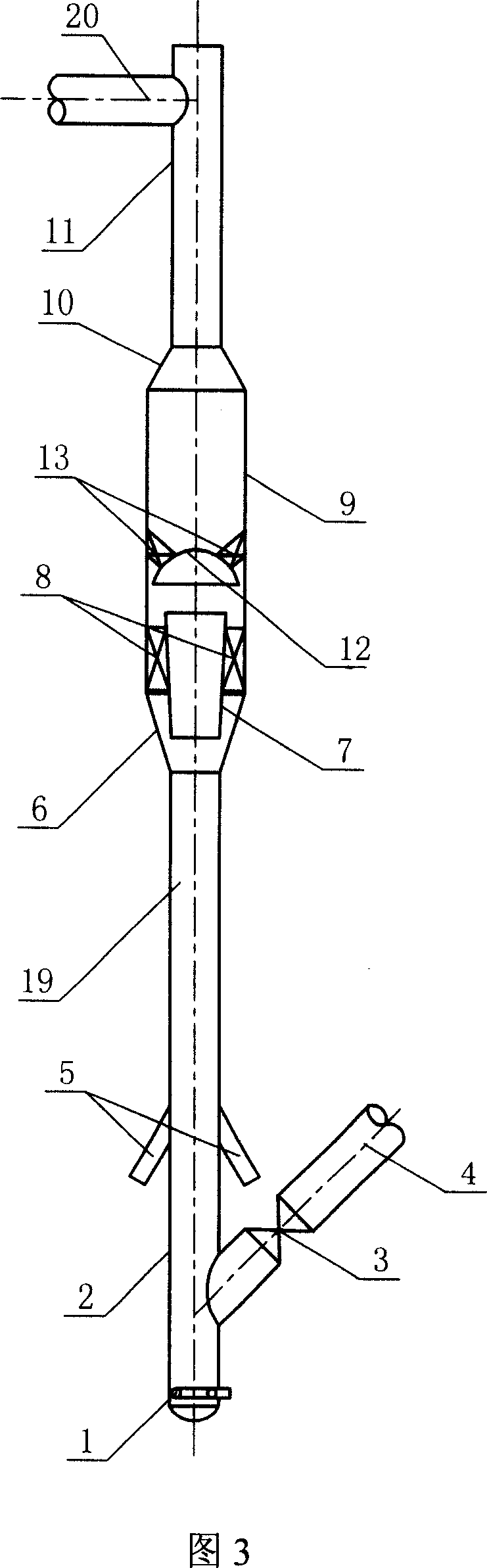
Image

Examples
Embodiment 1
[0039] This example illustrates the axial variation of the average density of the catalyst in the second reaction section of the riser measured by using the riser reactor shown in FIG. 3 provided by the present invention on the fluidized cold model experimental device.
[0040] The total height of the riser reactor used in the experiment is 13.5 meters, the inner diameter of the pre-lifting section is 0.25 meters, and the height is 2.5 meters; the inner diameter of the first reaction section is 0.2 meters, and the height is 4 meters; the inner diameter of the second reaction section is 0.5 meters, The height is 5 meters; the inner diameter of the outlet section is 0.2 meters, and the height is 2 meters; the cone top of the diameter expansion section between the first reaction section and the second reaction section and the diameter reduction section between the second reaction section and the outlet section The angles are all 60°; the outer diameter of the lower end of the draf...
Embodiment 2
[0042] This example illustrates the axial variation of the average density of the catalyst in the second reaction section of the riser measured through experiments using the riser reactor shown in FIG. 4 provided by the present invention on the fluidized cold model experimental device.
[0043] The total height of the riser reactor used in the experiment is 13.5 meters, the inner diameter of the pre-lifting section is 0.25 meters, and the height is 2.5 meters; the inner diameter of the first reaction section is 0.2 meters, and the height is 4 meters; the inner diameter of the second reaction section is 0.5 meters, The height is 5 meters; the inner diameter of the outlet section is 0.2 meters, and the height is 2 meters; the cone top of the diameter-expanding section between the first reaction section and the second reaction section and the shrinking section between the second reaction section and the outlet section The angles are all 90°; the height of the frustum-shaped draft ...
Embodiment 3
[0045] This example illustrates how the average density of the catalyst in the second reaction section of the riser varies along the axial direction measured through experiments using the riser reactor shown in FIG. 6 provided by the present invention on the fluidized cold model experimental device.
[0046] The total height of the riser reactor used in the experiment is 13.5 meters, the inner diameter of the pre-lifting section is 0.25 meters, and the height is 2.5 meters; the inner diameter of the first reaction section is 0.2 meters, and the height is 4 meters; the inner diameter of the second reaction section is 0.5 meters, The height is 5 meters; the inner diameter of the outlet section is 0.2 meters, and the height is 2 meters; the cone angle of the expanding section connecting the first reaction section and the second reaction section is 60°, and the The cone angles of the reduced diameter sections between them are all 120°; the total height of the combined draft pipe is...
PUM
| Property | Measurement | Unit |
|---|---|---|
| height | aaaaa | aaaaa |
| height | aaaaa | aaaaa |
| height | aaaaa | aaaaa |
Abstract
Description
Claims
Application Information