

Thermal-shrinkage tube expanding mould
A heat-shrinkable tube and mold technology, which is applied in the field of heat-shrinkable tube expansion molds, can solve problems such as high manufacturing costs, limited expansion speed, and poor mold cooling effect, and achieve good cooling effect and stable expansion
- Summary
- Abstract
- Description
- Claims
- Application Information
AI Technical Summary
Problems solved by technology
Method used
Image

Examples
Embodiment Construction
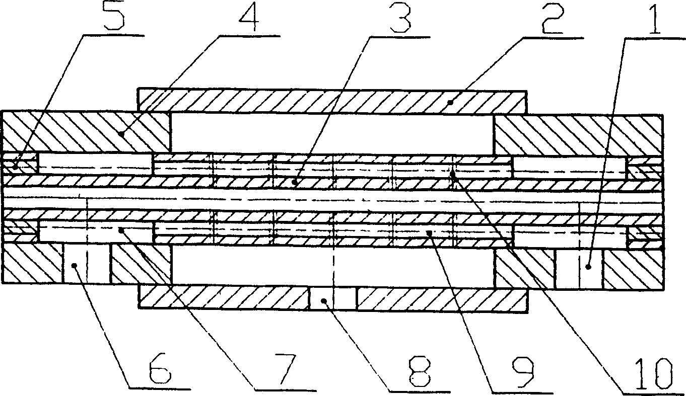
[0012] In Fig. 1, there are two long cooling holes (9) parallel to the axis of the sizing pipe (3), both ends of the long cooling holes (9) are blocked with plugs (5), and the sizing pipe (3) There are cooling water rings (7) on both sides of the cooling water ring (7), a cooling water jacket (4) on the outside of the cooling water ring (7), a vacuum jacket (2) on the outside of the cooling water jacket (4), and two There are 5 rows of vacuum holes (10) between the two cooling water rings, cooling water outlet (6) on the left cooling water jacket (4), cooling water inlet (1) on the right cooling water jacket (4), vacuum Vacuum suction port (8) is arranged on cover (2).
[0013] The cooling water enters the right cooling water ring (7) from the cooling water inlet (1), reaches the left cooling water ring (7) through the cooling long hole (9), and flows out through the cooling water outlet (6). tube to cool. A closed space is formed between the vacuum jacket (2), the cooling w...
PUM
 Abstract
Description
Claims
Application Information