Evaporator and heat absorber of separated gravity hot pipe

A gravitational heat pipe and evaporator technology, applied in indirect heat exchangers, lighting and heating equipment, etc., can solve the problems of large liquid inflow, unfavorable heat transfer, and large liquid working mass, etc. good thermal effect

Inactive Publication Date: 2007-09-05
庞立升
View PDF3 Cites 12 Cited by
  • Summary
  • Abstract
  • Description
  • Claims
  • Application Information

AI Technical Summary

Problems solved by technology

The disadvantage of using this scheme is that the liquid working medium undergoes pool boiling evaporation in the lower half of the evaporating tube, and the upper half of the tube wall is not wetted by the liquid working medium and no phase change heat occurs, so the upper half of the evaporating tube cannot be fully utilized. heat exchange surface
There are defects in this patent: in the implementation process, possible small errors make the upper ports of the "channels" not at the same height, and the absolute values ​​of the areas of the liquid inlets of each channel immersed in the liquid are quite different, as shown in Figure 11, Figure 12, Figure 13, then, the absolute value of the liquid intake also differs greatly. During start-up

Method used


Image

  • Evaporator and heat absorber of separated gravity hot pipe
  • Evaporator and heat absorber of separated gravity hot pipe
  • Evaporator and heat absorber of separated gravity hot pipe

Examples


Embodiment 1

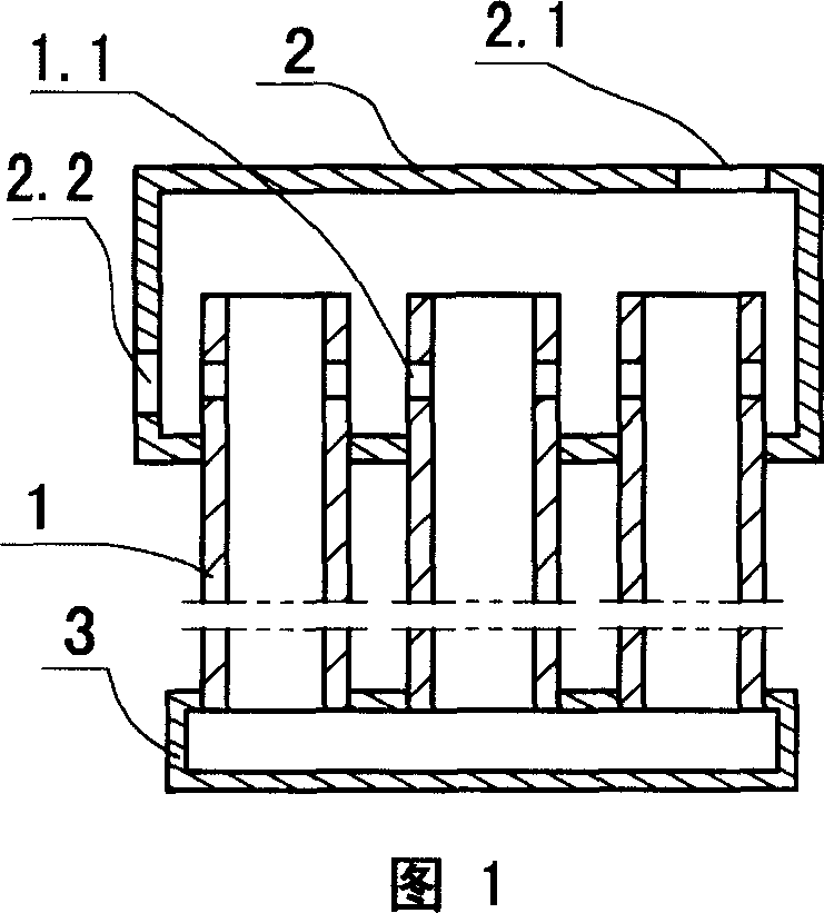
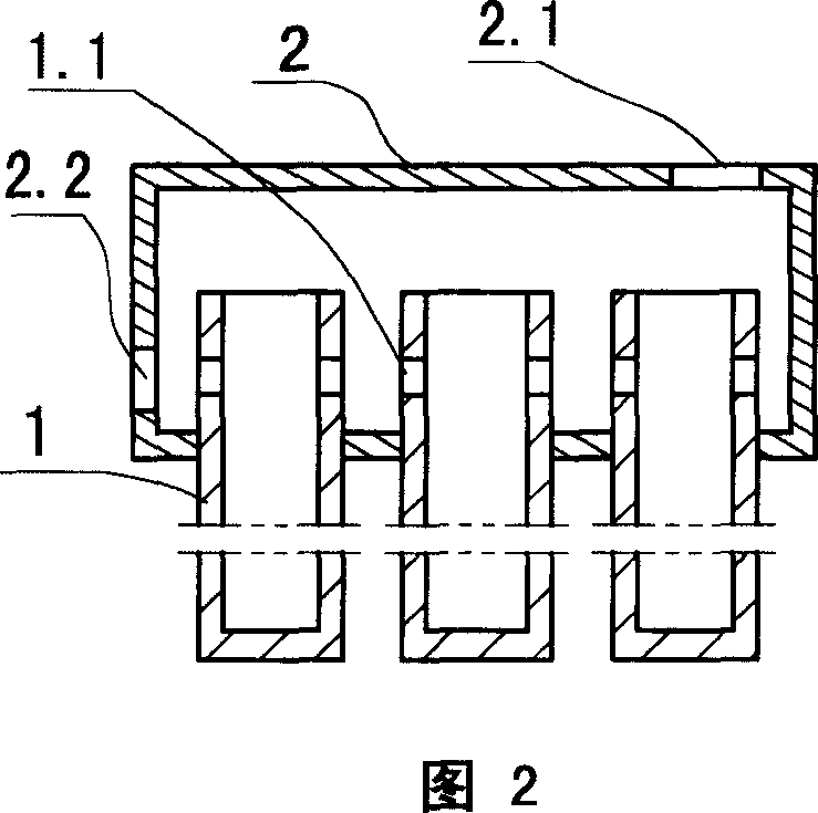
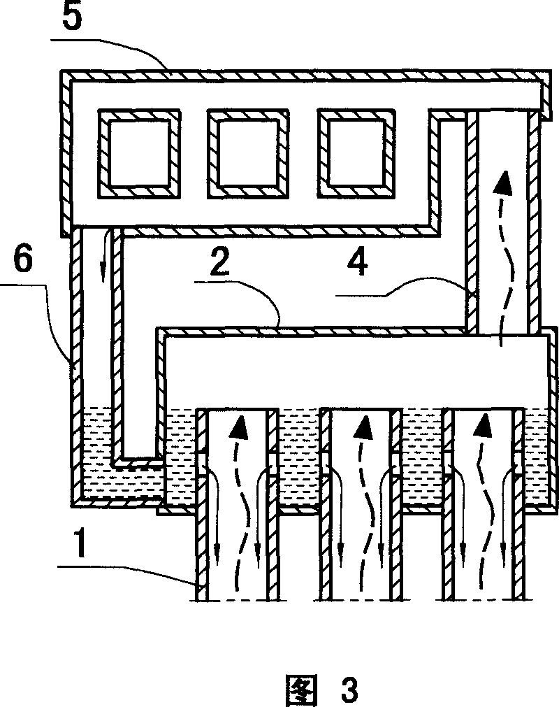
[0039] The evaporator adopting technical scheme A or technical scheme B is used for the separated heat pipe system, the steam outlet (2.1) of the evaporator is connected with the steam rising pipe (4) of the heat pipe system, and the liquid inlet (2.2) of the evaporator is connected to the heat pipe The liquid return pipe (6) of the system is communicated, as accompanying drawing 3. Evaporator can adopt any form shown in accompanying drawing 1, accompanying drawing 2.

[0040] If there is no error during implementation, it can be ensured that the upper ports of all the evaporation tubes (1) are at the same height, and it can be used in occasions where the heat load is fixed or where the heat load varies.

[0041] If there is an error during implementation, it can be used in situations where the thermal load changes within a certain range, and is described with technical solution A. In contrast to what is stated in the "Content of the Invention" of this manual, the position of...

Embodiment 2

[0048] Adopt technical scheme C or technical scheme D heat pipe type heat absorber. For the occasion of fixed heat load, the heat pipe heat absorber of technical scheme C or technical scheme D is feasible.

[0049] If there is no error during implementation, it can be ensured that the upper ports of all the evaporation tubes (1) are at the same height, and it can be used in occasions where the heat load is fixed or where the heat load varies.

[0050]If errors occur during implementation, it can be used in situations where the heat load varies within a certain range. The analysis of the technical solution C is the same as that of the technical solution A of the first embodiment.

[0051] In the case of small full load, when the implementation is prone to errors, technical scheme D should be adopted, and a capillary fabric block (12) can be arranged at the bottom of the upper header (2), and the capillary fabric strip (8) and the capillary fabric block (12 ) braided together. ...

Embodiment 3

[0055] As shown in accompanying drawing 10, the technical scheme is: multiple evaporators of the separated gravity heat pipe of the present invention are matched with a condenser to form a separated heat pipe system, with a liquid distribution box (10) and several liquid distribution pipes ( 9) Evenly distribute the reflux liquid of the condenser to each evaporator. The specific pipeline is that the steam outlet (2.1) of each evaporator is connected to a steam rising pipe (4), and the steam rising pipes (4) of all evaporators are connected to the steam main pipe (11), and the steam main pipe (11) is connected to the condensing pipe. The steam inlet of the condenser; the liquid outlet of the condenser is connected to the liquid return pipe (6), and the other end of the liquid return pipe (6) is connected to the liquid distribution tank (10); the upper ends of several liquid distribution pipes (9) extend into the liquid distribution tank (10) In the inner cavity, the liquid dist...


PUM


Abstract

It's a kind of evaporator of separating gravity heat pipe, which can make reflux condensed fluid in the hot pipe distribute uniformly on the evaporating pipe, and form falling film evaporation. The essentials of technological scheme are that the evaporator includes at least two evaporation tubes (1) and a upper header, and the part of the evaporation tube (1) in which there are liquid inlet holes (1.1) trends into the upper header (2), the upper ends of evaporators are the same height, so are the liquid inlet holes (1.1); outlet steam (2.1) and liquid inlet opening (2.2) are installed on the upper header; the openings of the evaporator (1) can be in its lower end, and all connect with sub-header; the evaporator (1) can be sealed in its lower end.

Description

Technical field [0001] The invention relates to an evaporator and a heat absorber of a separated gravity heat pipe, adopting a new structure, which can well solve the problem of evenly distributing the reflux condensed liquid of the separated heat pipe to the upper ends of each evaporation pipe to form falling film evaporation. Background technique [0002] The separated gravity heat pipe system has two or more evaporating tubes as the evaporating section, and the condensing section can be a single or multiple serpentine coils as the condensing section, and the steam rising pipe and the liquid return pipe are connected in the middle. [0003] According to the existing technical situation, according to the search, "separated heat pipe system (patent number CN98100172.6)", the condenser and the evaporator are arranged separately, and the condenser and the evaporator are connected by a steam riser pipe and a liquid return pipe. The main points of the technical solution are as fo...

Claims


Application Information

Patent Timeline
IPC IPC(8): F28D15/02F28D15/04
CPCF28D15/0266
Inventor 庞立升
Owner 庞立升
Why Eureka
Try Eureka