
LED luminescent pen

A light-emitting pen and light-emitting diode technology, applied in the field of writing pens, can solve problems such as poor contact, LED light flickering, short length, etc., to achieve the effect of increasing applicability and solving LED flickering

Inactive Publication Date: 2007-09-12
NINGBO DYMAX
View PDF3 Cites 8 Cited by
  • Summary
  • Abstract
  • Description
  • Claims
  • Application Information

AI Technical Summary

Problems solved by technology

In the above two patents, the battery, light-emitting diode and refill are respectively arranged at the rear, middle and front of the penholder, which has two disadvantages: one is that the light-emitting diode illuminates the middle part of the penholder and its surroundings, Instead of being concentrated around the nib, its decorative function is more than practical; second, due to the limited position, the pen core is short in length and holds less ink, so it is easy to use up and needs to be replaced frequently, so it is not practical enough.
[0004] But the top of the refill in this LED luminescent pen directly contacts with the negative end of the battery, and the positive end of the battery contacts with the switch assembly again. Pressure, this pressure is directly transmitted from the refill to the battery, and then to the switch assembly located above the battery, because people use different forces when writing, and the direction of force is also uncertain, and often requires deflection. It is easy to cause the switch assembly to move relative to the pen holder, which will affect the good conduction between the switch assembly and the pen holder, or the contact piece in the pen holder, resulting in the flickering of the LED when writing, and cannot stabilize the light. At the same time, in the continuous writing process In the process, the conductive contact between the switch assembly and the pen holder, the pen core and the negative terminal of the battery are also worn out, which is likely to cause poor contact and affect the normal luminescence of the LED; sometimes, when people write too hard, or the LED Accidental drop of the luminous pen causes the refill to be subject to a large pressure, which will easily lead to damage to the switch assembly and make the LED luminous pen unable to work normally
[0005] On the other hand, the LED luminescent pen uses the top of the refill as a conductive part to conduct the negative electrode of the battery to the boost circuit. The top of the refill must be made of metal materials, and most of the refills on the market There are many non-metal shells used in the whole body, so the applicability of this LED luminous pen is not very strong

Method used


Image

  • LED luminescent pen
  • LED luminescent pen
  • LED luminescent pen

Examples


Embodiment 1

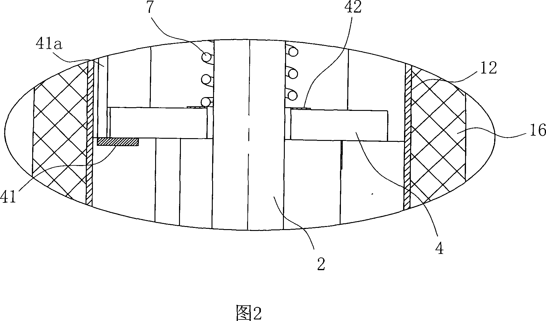
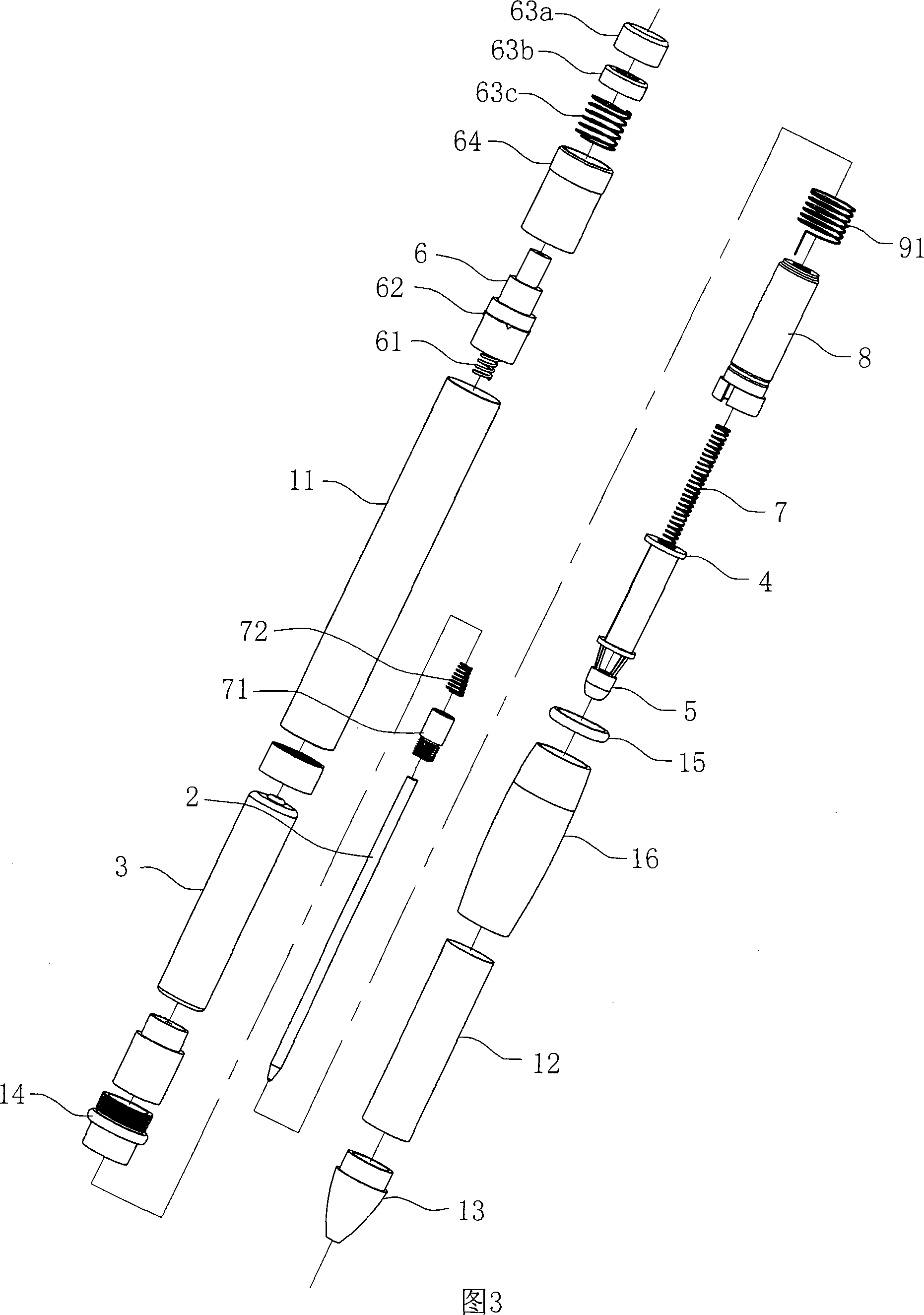
[0041] As shown in Figures 1 to 3, it is an LED light-emitting pen using a column battery as a power source, including a pen holder 1 and a refill 2 set in the pen holder 1, a battery 3, a light-emitting circuit board 4, and a connection with the light-emitting circuit board 4 the LED 5;

[0042] In this embodiment, the battery 3 is a cylindrical battery, and the light-emitting circuit board 4 is equipped with a booster module, so that a common 1.5V cylindrical battery can also make the light-emitting diode 5 emit light;

[0043] The penholder 1 includes an upper penholder 11, a middle penholder 12 and a lower penholder 13, the three are sequentially connected into one from top to bottom, the battery 3 is located in the upper penholder 11, that is, the upper part of the penholder 1, the light-emitting circuit board 4 and its The light-emitting diode 5 is arranged at the bottom of the penholder 1, and the lower penholder 13 is a transparent non-metallic material, the light-emit...

Embodiment 2

[0054] As shown in FIG. 4 , it is the second embodiment of the present invention. The difference from the first embodiment is that the battery 3 uses three button batteries connected in series, and the light-emitting circuit board 4 does not need a booster module.

Embodiment 3

[0056] As shown in Figure 5, it is the third embodiment of the present invention. The difference from the first embodiment is that the rotating assembly 8 uses a one-way rotating member to realize the entry and exit of the pen core 2 in the pen holder 1. Due to the one-way rotation The structure and shape of the parts and the Coats rotating parts are all different, the shapes of the light-emitting circuit board 4 and the light-emitting diode 5 of the LED light-emitting pen are slightly different, and the structure of the metal refill cap 71 is also different;

[0057] And in this embodiment, the middle penholder 12 must be made of metal material to participate in the LED light-emitting circuit, and the electrical connection between the upper penholder 11 and the positive input terminal 41 of the light-emitting circuit board 4 is realized by the following settings: the positive pole of the light-emitting circuit board 4 The input end 41 is in contact with the middle penholder 12...


PUM


Abstract

The light emitting LED pen includes a pen holder, a refill inside the pen holder, a battery, a light emitting circuit board, a LED, and a rotating assembly for shifting the refill up and down. The pen holder includes an upper part and a lower part of transparent non-metal material; the battery has positive pole connected electrically to the positive input end of the light emitting circuit board via conductor and negative pole connected electrically to the conducting spring via the metal refill cap and the negative pole spring, and the conducting spring has bottom end contacting the negative input end of the light emitting circuit board. The light emitting LED pen has stable lighting without being affected by the writing force.

Description

technical field [0001] The invention relates to a writing pen with an illuminating device, in particular to an LED luminous pen with LED (light emitting diode) as the illuminating light source. Background technique [0002] In recent years, with the rapid development of LED technology, many LED luminous pens with LED as the light source have appeared on the market. This kind of LED luminous pen has a light source, so that the original ordinary pen can be used as a miniature pen. Flashlight, help to write in the dark, find items, watch watches or read letters and other purposes, some LED luminous pens also design the LED light-emitting components into various colors and various flashing methods, so that the luminous effect of the LED luminous pen is more beautiful , are becoming more and more popular. For example, among the Chinese utility model patents, the patent No. is ZL02200769.5 (announcement number is CN2520256Y) and the patent No. is ZL03253042.0 (announcement number...

Claims


Application Information

Patent Timeline
Patent Type & Authority Applications(China)
IPC IPC(8): B43K29/10
CPCB43K24/06B43K29/10
Inventor 胡积献
Owner NINGBO DYMAX
Learn More