Mechanical plug-removal oil extraction device

A technology of mechanical plugging removal and oil extractor, which is applied in the direction of production fluid, earthwork drilling, wellbore/well components, etc., and can solve problems such as no function of plugging removal

Inactive Publication Date: 2007-09-12
邢立升
View PDF0 Cites 17 Cited by
  • Summary
  • Abstract
  • Description
  • Claims
  • Application Information

AI Technical Summary

Problems solved by technology

[0002] At present, the known downhole oil production tool

Method used


Image

  • Mechanical plug-removal oil extraction device
  • Mechanical plug-removal oil extraction device
  • Mechanical plug-removal oil extraction device

Examples


Embodiment 1

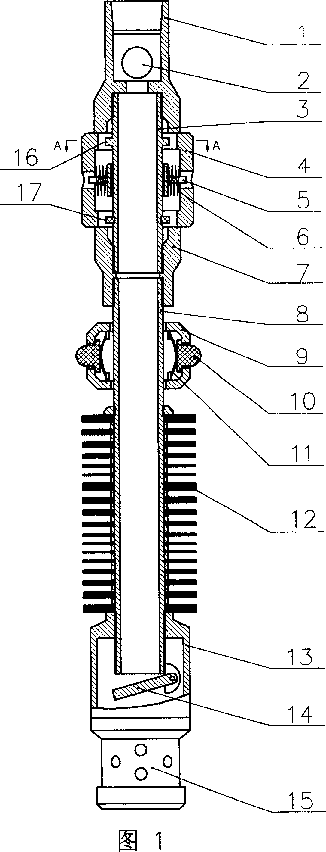
[0029] In Fig. 1, the upper end of the upper joint 1 is a female thread, which is connected with the lower oil pipe of the oil pump in the oil well, and the lower end is also a female thread, which is connected with the upper center pipe 3, and a forward check valve 2 is installed in the middle cavity; The middle and upper part of the center pipe 3 is provided with a boss 16, the middle part is set with the reducing piston assembly 4, the middle and lower part is equipped with a circlip 17, and the lower end is connected with the lower center pipe 8 through the lower joint 7; the inner cavity of the reducing piston assembly 4 is installed There are springs 6 and spring brackets 5; the upper part of the lower center tube 8 is fitted with a hollow vibrating ring assembly 9, the middle part is equipped with a vibrating plate group 12, the lower part is connected to the screen pipe 15 through the outer cylinder 13, and the reverse check valve 14 is installed at the bottom; the hollo...

Embodiment 2

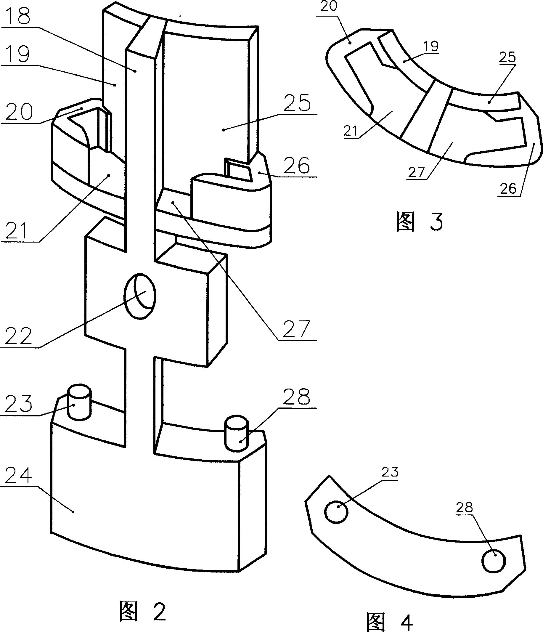
[0039] In Fig. 11, the upper and lower ends and the left and right sides of a single arc-shaped piston block are all equipped with a hook-shaped slideway stop baffle plate 20 and a pin shaft slideway 21.

[0040] In Fig. 12, pin shafts 23 are installed at the upper and lower ends and the left and right sides of a single arc-shaped piston block.

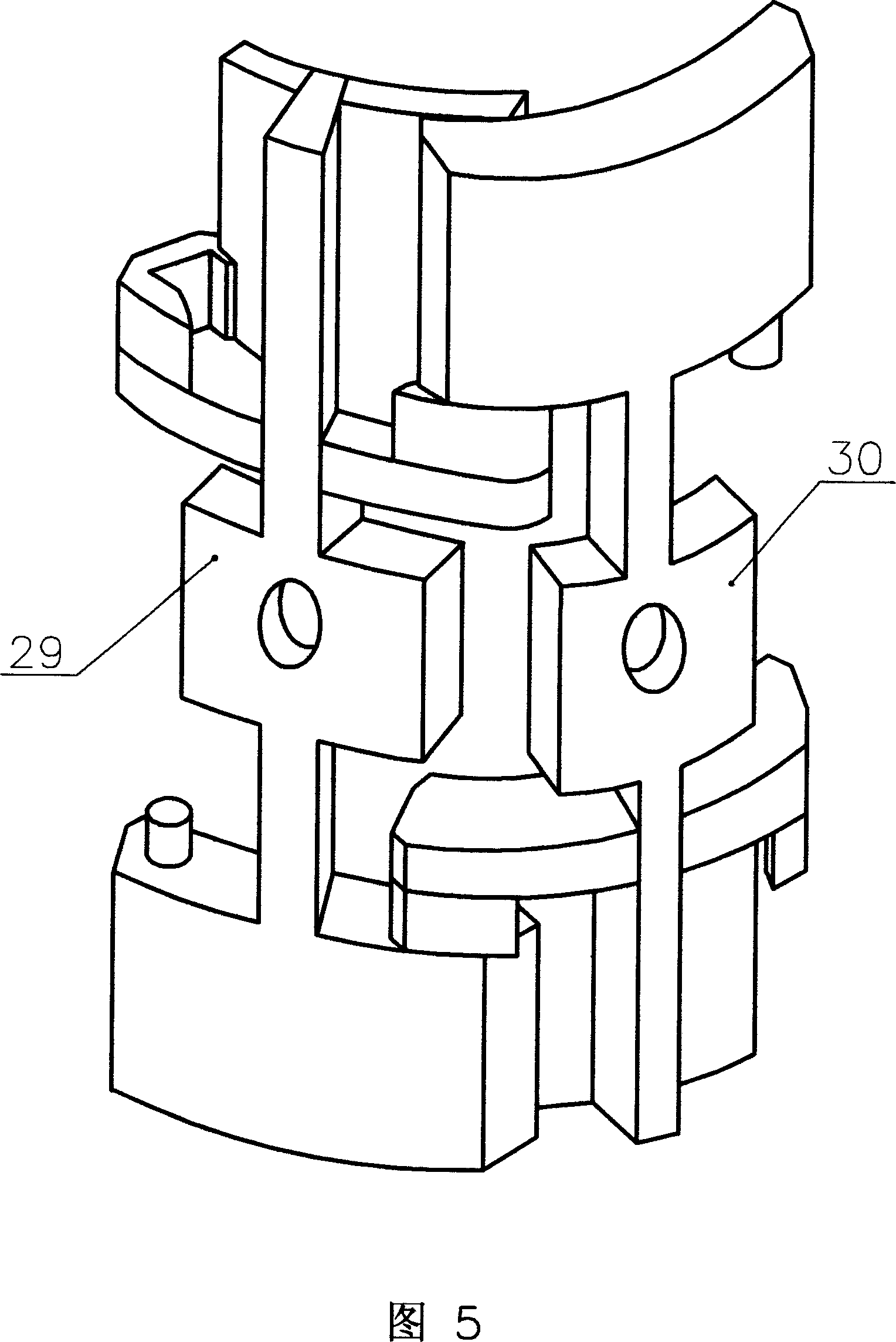
[0041] In Fig. 13, the left side is a single arc-shaped piston block 32 with a hook-shaped slideway stop baffle plate and a pin shaft slideway installed at the upper and lower ends and the left and right sides, and the right side is a single arc-shaped piston block 32 with the upper and lower ends and the left and right sides. A single arc-shaped piston block 33 of pin shaft is installed; as can be seen from Figure 13, a single arc-shaped piston block with hook-shaped slideway stop baffle and pin shaft slideway is installed at the upper and lower ends and the left and right sides 32 is snapped together with a single arc-shaped piston ...


PUM


Abstract

A mechanical relieving-chock packer which can improve oil yield of oil-well mechanism is composed of upper contact, positive uniflow valve, upper central tube, reducer plunger unit assemblage, lower contact, lower central tube, hollow vibration ring unit assemblage, vibrating plate set, outer tube, reverse uniflow valve and sieve tube etc. The reducer plunger unit assemblage is packaged on middle part of the upper central tube. The hollow vibration ring unit assemblage is packaged on upper part of the lower central tube. The vibrating plate set is equipped on middle part of the lower central tube. The invention is equipped in the bushing linking the oil pipe in lower part of oil-well pump. When the oil extractor is in upward stroke, the packer moves upward with the elastic shrinkage of the oil pipe, which strikes the hollow vibration ring unit assemblage to generate vibration wave. It also forms a high-pressure area in lower part of the reverse uniflow valve to generate a high-pressure hydrodynamic wave. It has the same process when the oil extractor is in downward stroke. The packer utilizes the cyclical elastic distortion of oil string to realize cyclical pulse-type alternating motion. It translates striking energy inside system and changing energy of liquid pressure into fluctuating energy, conducts it into the oil channel in the stratum and relieves oil-layer chock, which can enhance the oil yield.

Description

technical field [0001] The invention relates to a plugging-removing oil recovery device for petroleum oil wells, in particular to a mechanical plugging-removing oil recovery device capable of increasing oil well output. Background technique [0002] At present, the known downhole oil production tools can only pump oil, and have no function of removing plugs. Contents of the invention [0003] In order to enable the downhole oil production tool to have the function of unblocking, the present invention provides a mechanical unplugging oil extractor. The vibrating plate group of the mechanical unblocking oil extractor transmits powerful vibration energy into the oil layer, unblocks the oil well, clears the oil flow channel, creates an environment conducive to the flow of crude oil, and achieves the purpose of increasing the production of the oil well. [0004] The technical solution adopted by the present invention to solve the technical problem is: the upper joint, the forw...

Claims


Application Information

Patent Timeline
IPC IPC(8): E21B43/25E21B28/00
Inventor 邢立升
Owner 邢立升
Why Eureka
Try Eureka