Method of energy cumulative presplitting and smoothsurface blasting and special device therof

A technology of smooth blasting and special devices, applied in blasting, blasting cylinders, weapon accessories and other directions, can solve the problems of large harmful effect of retained rock mass, high cost, complex structure, etc., to enhance blasting force, reduce harmful effects, Simple and convenient operation

Active Publication Date: 2007-09-12
SINOHYDRO BUREAU 8 CO LTD
View PDF1 Cites 41 Cited by
  • Summary
  • Abstract
  • Description
  • Claims
  • Application Information

AI Technical Summary

Problems solved by technology

[0020] 1. Its biggest defect is that there is no "centering device", so the energy-gathering jet cannot be guaranteed to spray along the pre-split surface or the light-exploding surface, and the function of the energy-gathering jet cannot be fully exerted normally, and the energy-gathering jet cannot form a complete shaped jet surface
[0021] 2. The shaped charge rolls are generally circular, which does not change the force distribution of the explosive on the wall of the blast hole
[0022] 3. The structure is complex, the amount of drilling work in the construction is large, the cost is high, and the harmful effect on the retained rock mass is relatively large; it has no practical value and is difficult to be widely used in engineering
[0023] 4. Due to the above-mentioned problems, there are no reports of large-scale application of the above-mentioned pre-splitting and smooth blasting technologies

Method used


Image

  • Method of energy cumulative presplitting and smoothsurface blasting and special device therof
  • Method of energy cumulative presplitting and smoothsurface blasting and special device therof
  • Method of energy cumulative presplitting and smoothsurface blasting and special device therof

Examples


Embodiment Construction

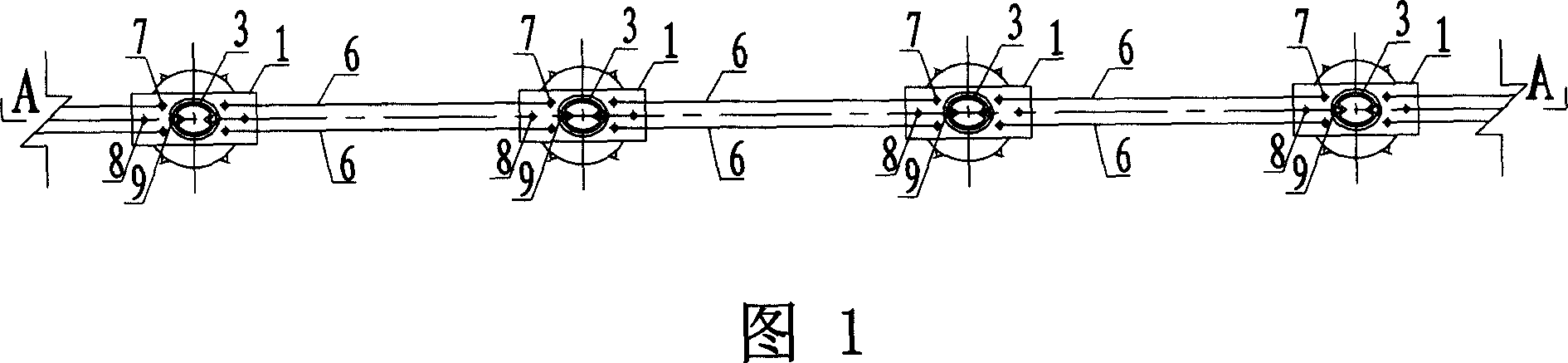
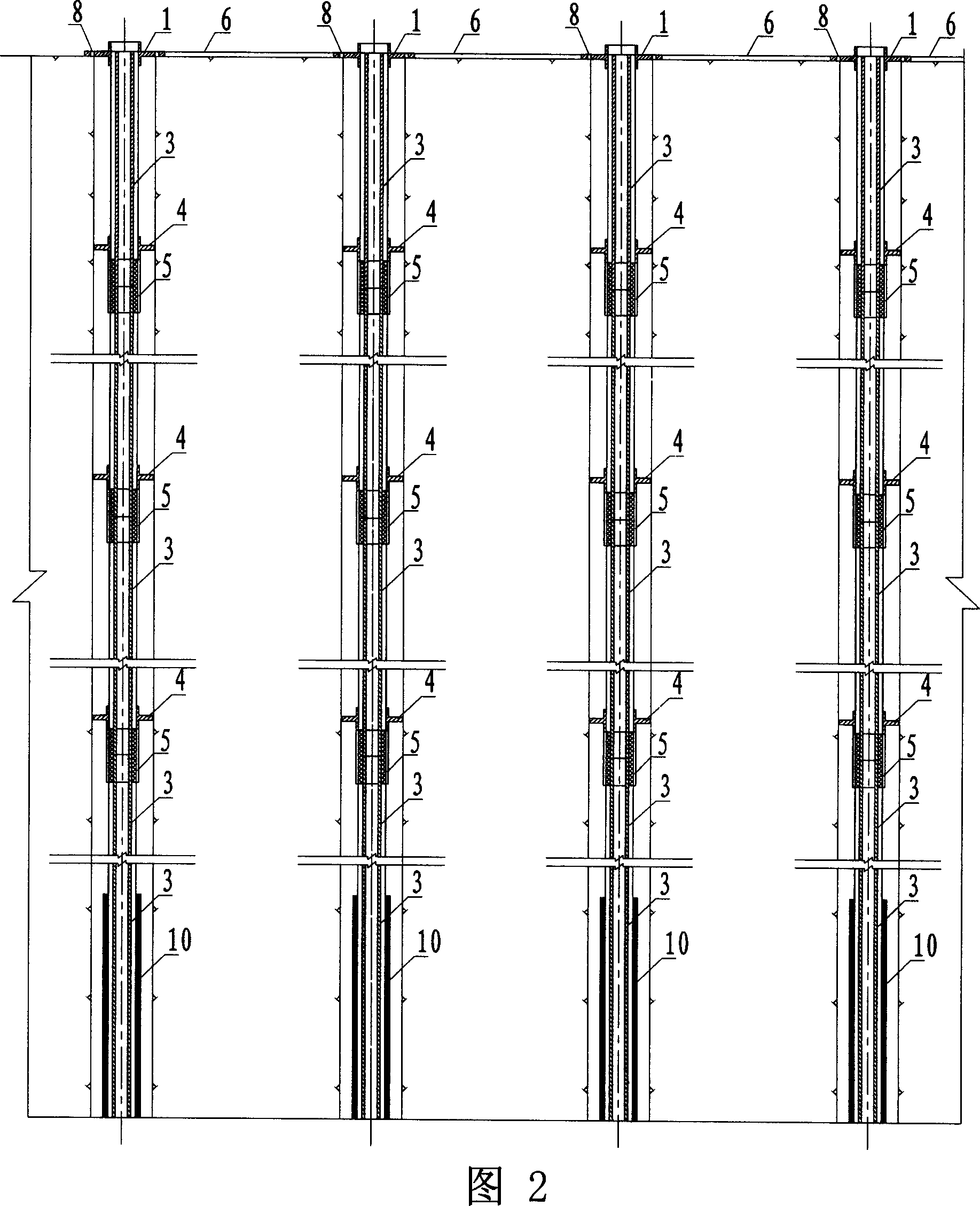
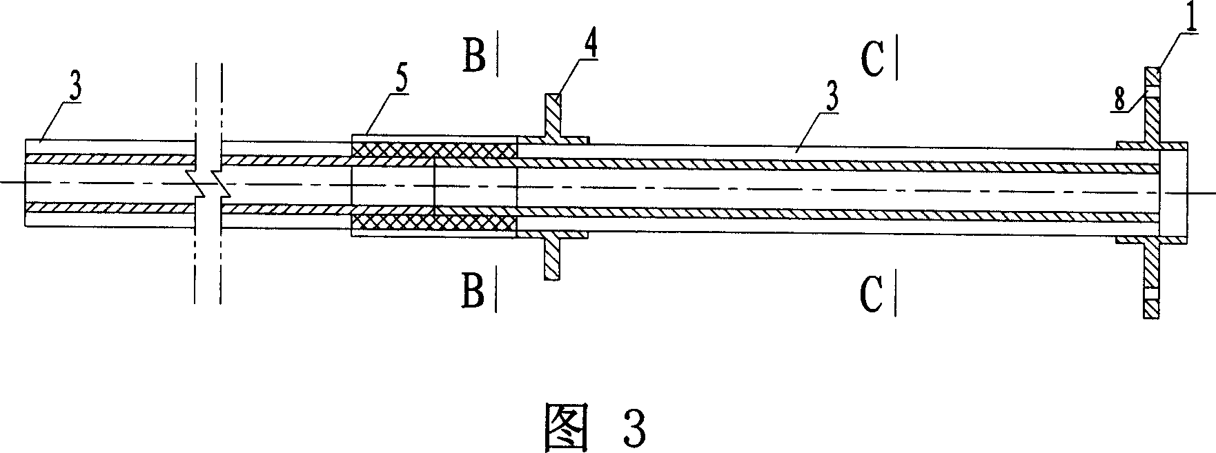
[0057] The dual-energy pre-splitting and smooth blasting method of the present invention uses the special device for dual-energy pre-splitting and smooth blasting as shown in Figures 1 to 11 to realize energy-gathering pre-splitting or smooth blasting.

[0058] The special device for dual-energy pre-splitting and smooth surface blasting of the present invention is shown in Figures 1 to 11. It includes a multi-section standard section 3 of the energy-collecting tube whose cross-sectional shape is an elliptical ring, and is sleeved on the standard section 3 of the energy-collecting tube to connect the head and tail phases. The connecting sleeve 5 of the standard section 3 of the two energy-collecting tubes connected, the centering ring 1 located at the orifice of the blasthole and the centering ring 4 located in the hole in the blasthole, and the standard section of each section of the energy-collecting tube is connected by the connecting sleeve 5 3. Make its length reach the dep...


PUM


Abstract

It is a special-purpose device used for two-directional energy-focusing and smooth blasting, post standard knot of multisection energy-gathering pipe which is in the double ''V'' shaped energy-accumulating groove which is set on the pipewall full of detonator, each post standard knot is linked with connection casing on which there is energy-accumulating groove, centering ring in the hole is noosed on the standard joint of the binding energy tube so that the center lines of the upper and the lower energy-gathering groove like V shape are in the same surface in the blasthole. Orifice centering rings of the two V- shaped central whose orientation is the same with V- shaped energy-gathering groove are set on the noose annulus wall at the ground end of energy -gathering pipe at orifice of blasthole, which makes the center line of each energy-gathering groove like a V shape forms a surface of centering and coinciding with blasting surface in each blasthole and among. After detonating explosive, make shaped charge jet spark along initial small crack that forms while the crack begins to form, then forms presplitting or smooth blasting surface, and finish energy-gathering presplitting and smooth blasting. The invention can enhance utilization ratio of demolishing energy and debase quantity of drilled holes, the influence of destroying rock mass kept down is little and the blasting surface is more level.

Description

technical field [0001] The invention belongs to the field of blasting construction, and in particular relates to a pre-splitting and smooth blasting method and device. Background technique [0002] In the late 1980s, those skilled in the art tried to use paper materials to process shaped-energy tubes to form shaped-energy rolls and did experimental research on shaped-energy pre-splitting blasting, but they could not be used in normal construction due to technical and technological limitations. For a long time, the experimental research on energy-concentrated presplitting blasting has been stagnant. After the 1990s, the vigorous development of hydropower development and the large-scale development of national capital construction, the needs of engineering construction have caused scholars to have a strong interest in the experimental research of energy-gathering pre-splitting blasting, and it is in the ascendant in recent years. Many scientific and technological workers have...

Claims


Application Information

Patent Timeline
Patent Type & Authority Applications(China)
IPC IPC(8): F42D1/00F42B3/22
Inventor 秦健飞
Owner SINOHYDRO BUREAU 8 CO LTD
Why Eureka
Try Eureka