
Down-transmission type centrifugal extractor for the chemical industry operation

An extractor and transmission type technology, applied in the field of lower transmission type centrifugal extractor, can solve the problems of loss of precision of centrifugal drum, troublesome replacement method, unusable equipment, etc., so as to achieve the problem of not destroying processing precision, prolonging service life and running smoothly. Effect

Inactive Publication Date: 2007-09-19
THUNIP HLDG
View PDF0 Cites 8 Cited by
  • Summary
  • Abstract
  • Description
  • Claims
  • Application Information

AI Technical Summary

Problems solved by technology

[0003] But the disadvantages of the above-mentioned top-suspended centrifugal extractor currently used are: (1) Since the selection of the size of the heavy phase weir is determined according to the difference in gravity, viscosity and flow ratio between the two phases of the material, different materials and operating conditions require Different sizes of heavy phase weirs are used to adjust, so different material properties and process conditions must be replaced with different sizes of heavy phase weirs, so this centrifugal extractor is equipped with or customized heavy phase weirs of different sizes to meet the process requirements, but above When replacing the phase weir of the suspended centrifugal extractor, the upper transmission mechanism and the connected drum must be hoisted out together, and then the drum is removed to replace the phase weir. After the replacement, the drum is reinstalled together with the transmission mechanism. To the original position, the replacement method is troublesome, and the accuracy of the centrifugal drum will be lost every time it is disassembled, so some companies do not replace the phase weir, which may cause the equipment to not work under the most suitable conditions, which is harmful to centrifugal extraction. The use of the device is a big waste, and some companies even think that the device cannot be used because the phase weir is not suitable and cannot meet the process requirements.
(2) The current centrifugal extractor is a top-suspension type, that is, the transmission part is on the upper part of the equipment, together with the motor, it accounts for most of the weight of the whole equipment, which is four-fifths of the weight of the main body
Makes the whole set look bulky

Method used


Image

  • Down-transmission type centrifugal extractor for the chemical industry operation

Examples


Embodiment Construction

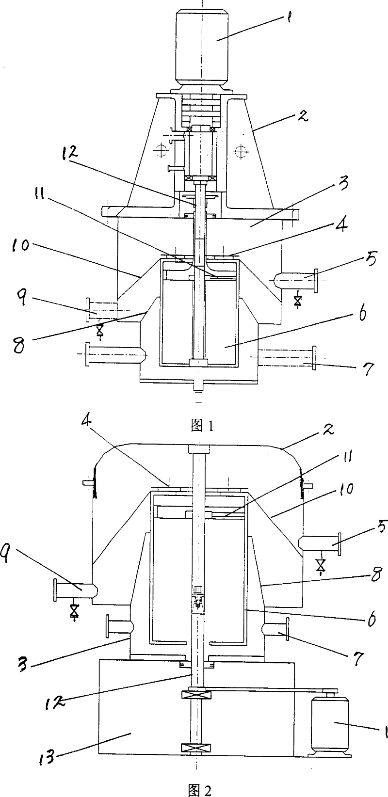
[0011] The structure of the lower drive type centrifugal extractor for chemical industry operation proposed by the present invention is shown in FIG. The upper cover 2 is built-in and covered on the shell 3 of the extractor. The rotating drum 6 is installed in the center of the extractor shell 3, and the extractor shell 3 is buckled on the rotating drum 6, and the rotating drum 6 is linked with the motor 1 through the rotating shaft 12. A heavy phase collection ring 10 and a light phase collection ring 8 are provided between the extractor shell 3 and the drum shell 6, and a heavy phase outlet is provided on the extractor shell between the heavy phase collection ring 10 and the upper cover 2 of the extractor shell 5. A light phase outlet 9 is provided on the extractor shell between the heavy phase collection ring 10 and the light phase collection ring 8, and a two-phase inlet 7 is provided on the extractor shell between the light phase collection ring 8 and the bottom of the ex...


PUM


Abstract

The invention relates to a drive-type centrifugal extractor for use in chemical industrial operation, which belongs to the chemical processing equipment field, comprising a mixing tank, a rotary drum, and a motor. The mixing tank and the rotary drum are coaxially mounted on the machine base, the mixing tank covers the rotary drum in reverse to make the rotary drum in the mixing tank, and the rotary drum is linked with the motor via a rotating shaft. Between the outer shell of the mixing tank and the outer shell of the rotary drum are arranged a heavy-phase collection ring and a light-phase collection ring, a heavy phase outlet is arranged on the mixing tank outer shell between the heavy-phase collection ring and the upper cover of the mixing tank, and a light phase outlet is arranged on the mixing tank outer shell between the heavy-phase collection ring and the light-phase collection ring, and on the mixing tank outer shell between the light-phase collection ring and the bottom of the mixing tank are arranged two inlets. In the invention, the motor and the transmission parts are provided on the bottom of the main machine, which makes the weight of the machine shift downwards to the bottom. The centrifugal extractor is provided with compact structure, stable operation, and more convenient utilization and maintenance, and the rotary drum may not be disassembled when replacing phase barrage, thereby the centrifugal extractor is suitable for use in large-scale equipment.

Description

technical field [0001] The invention relates to a lower-drive centrifugal extractor used in chemical industry operations, belonging to the technical field of chemical equipment. Background technique [0002] The existing top-suspension centrifugal extractor used in chemical industry operations, that is, a single single-stage centrifugal extractor, is a high-efficiency equipment that integrates mixing and clarification. Its structure is shown in Figure 1. In Figure 1, 1 is Motor, 2 is the upper cover, 3 is the mixing tank, 4 is the heavy phase weir, 5 is the heavy phase outlet, 6 is the drum, 7 is the two-phase inlet, 8 is the light phase collection ring, 9 is the light phase outlet, 10 is Heavy phase collecting ring, 11 is light phase weir, and 12 is rotating shaft. It can be seen from the figure that it allows the liquid-liquid two phases to be fully mixed without affecting the separation of the two phases in the equipment. At the same time, the mixed phase in the same equ...

Claims


Application Information

Patent Timeline
IPC IPC(8): B01D11/00
Inventor 李京莲李慎文李星文
Owner THUNIP HLDG
Learn More