Elevator control device

A control device, elevator technology, applied in the field of elevator control devices, to achieve the effect of preventing abnormal tilt

Inactive Publication Date: 2007-09-19
MITSUBISHI ELECTRIC CORP
View PDF3 Cites 7 Cited by
  • Summary
  • Abstract
  • Description
  • Claims
  • Application Information

AI Technical Summary

Problems solved by technology

[0013] However, in this structure, the car 2 is suspended on the main cable 13 through the pulley 201, which is the same as the structure disclosed in Japanese Patent Laid-Open No. 6-64863, so there is no difference between the brake 11L or 11R on either side. In the case of operation, the same problem that the car 2 cannot be stopped

Method used


Image

  • Elevator control device
  • Elevator control device
  • Elevator control device

Examples


Embodiment 1

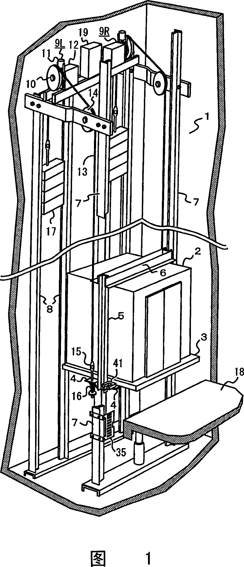
[0041] 1 to 11 show Embodiment 1 of an elevator control device having a plurality of hoisting machines according to the present invention. In this embodiment 1, two hoisting machines are specially arranged on the top of the elevator shaft, and the target lifting distance from the departure floor to the destination floor is jointly given to each hoisting machine to match the remaining distance from the current position to the destination floor. The speed is individually controlled for each hoist.

[0042]Fig. 1 is a perspective view showing the whole of an elevator control device. In the figure, 1 is the elevator shaft, 2 is the car, 3 is the floor of the car, 4 is the lower frame supporting the floor 3 of the car, 5 is the vertical frame erected on the left and right sides of the car 2, and 6 is the horizontal frame. The upper frame above the car 2. 7 is a pair of car guide rails fixed upright on the side walls of the elevator shaft on both sides of the car 2, and 8 is a cou...

Embodiment 2

[0082] 12 to 15 show Embodiment 2 of an elevator control device having a plurality of hoisting machines according to the present invention.

[0083] In this embodiment 2, at the beginning when the operation command is issued, the speed command is calculated as time goes by, and the winch is controlled uniformly. control.

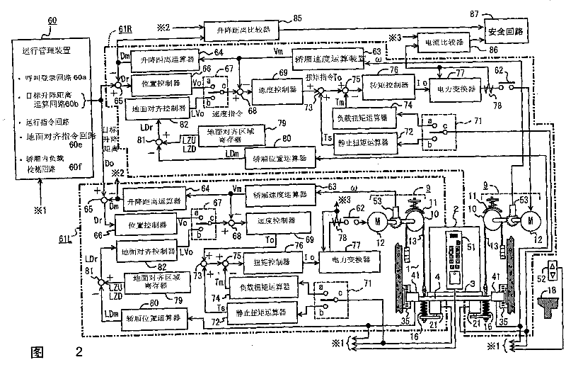
[0084] Fig. 12 is a circuit block diagram showing the control device of the elevator, and 91 is a pair of left and right grating plates installed on the car guide rail 7 with the length facing the up and down direction. As shown in Fig. 13 in detail, from the up and down deceleration points PPu, PPd Cutting groove 36 is formed until the position of the floor ground. 100 is an operation management device, including: call registration circuit 60a; operation command circuit 60c; ground alignment command circuit 60e; car load detection circuit 60f; and optical sensor 41 and grid plate 91 A deceleration command circuit 60d that engages and issues a deceleration ...

Embodiment 3

[0100] Fig. 16 is a third embodiment of the elevator control device of the present invention.

[0101] In Embodiments 1 and 2 described above, the counterweights 17 are suspended on the left and right, respectively. In Embodiment 3, a common counterweight is suspended by the left and right main cables 13L and 13R. That is, both ends of the main cables 13L and 13R are fixed to the common car 2 and the common counterweight 17A.

[0102] In the above-mentioned third embodiment, the weight of the counterweight 17A is set in the same manner as in the first embodiment, and even if one of the brakes 11 does not operate, the car 2 with the rated load Wf can be brought to a standstill by only the other brake 11 . Especially in the present embodiment 3, the counterweight 17A is common to the left and right main cables 13L, 13R, so only a pair of counterweight guide rails 8 is sufficient, which can reduce the installation work.


PUM


Abstract

An elevator control device, which can fasten a main cable at multiple portions of the compartment lifting in the lifting well, and wind the main cable on multiple windlasses upward arranged correspondingly to drive the compartment to lift, characterized in that with respect to the main cable fixing portions, the control device can detect the difference between the storey floor and the compartment floor when the compartment arrives at the destination storey, when the detection value exceeds the specified value, the corresponding windlasses will be used to drive the main fixing portions to move upward and downward respectively, thus to align the floor and reduce the difference. Therefore, even though the windlasses make the main cable move relatively and make the compartment floor incline, the inclination can be corrected by aligning the floors, so that the relative movement of the main cable will not accumulate.

Description

[0001] This application is a divisional application of the patent application whose application number is 02822781.6 and the application date is September 11, 2002. technical field [0002] The present invention relates to a control device for an elevator that utilizes a plurality of hoisting machines to lift and drive a car. Background technique [0003] In conventional elevators, the car is driven by a single hoist, so the capacity of the hoist increases as the load increases. Therefore, a large elevator requires a large hoist, and its installation requires a large-capacity crane. [0004] For this reason, for example, Japanese Patent Laying-Open No. 6-64863 discloses a pulley is set on the car, the main cable is wound up on the pulley, and the structure is driven by 2 small hoisting machines. [0005] Fig. 17 shows the same structure as that disclosed in the above-mentioned Japanese Patent Application Laid-Open No. 6-64863, and shows a conventional elevator in which the ...

Claims


Application Information

Patent Timeline
Patent Type & Authority Applications(China)
IPC IPC(8): B66B1/40B66B7/06
Inventor 安江正德
Owner MITSUBISHI ELECTRIC CORP
Why Eureka
Try Eureka