Method and apparatus for realizing load voltage regulation with a plurality of switching elements

A switching element and voltage regulation technology, which is applied in the direction of output power conversion devices, electrical components, transformers, etc., can solve the problems of regular maintenance of tap changer devices, high price of OLTC tap changers, and easy damage

Inactive Publication Date: 2007-09-19
魏明
View PDF1 Cites 24 Cited by
  • Summary
  • Abstract
  • Description
  • Claims
  • Application Information

AI Technical Summary

Problems solved by technology

[0002] At present, the known on-load tap-changing transformer realizes the on-load voltage regulation by switching the contacts of the on-load tap-changer. The price of the on-load tap-changer is high, and the tap-changer device needs regular maintenance, otherwise it is easy to be damaged. However, the power supply through the transformer will be completely interrupted when repairing the tap changer device or its damage; connecting the reactor in series on the AC line can also change the voltage of the load. When the load changes, the inductance of the reactor connected in series should be changed accordingly. In order to keep the load voltage stable, the on-load voltage regulation can also be realized by connecting the movable end of the tap or transfer switch to different taps of the series reactor. The existing problems are the same as those of the on-load tap changer. The problem of load voltage regulation is the same; application number is 02106678.7 invention patent disclosed power-saving device, and the problem existing in the voltage regulation winding of Japan Mu Electric's automatic voltage regulation and energy-saving motor with the same principle is the same as the above problem

Method used


Image

  • Method and apparatus for realizing load voltage regulation with a plurality of switching elements
  • Method and apparatus for realizing load voltage regulation with a plurality of switching elements
  • Method and apparatus for realizing load voltage regulation with a plurality of switching elements

Examples


Embodiment Construction

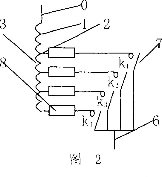
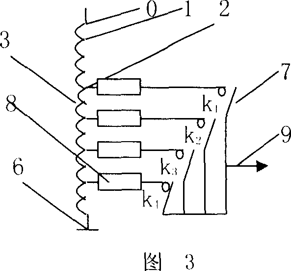
[0025] In the embodiment of Fig. 2, the main contact of an electromagnetic switching element (7) is connected to each tap (2) of the voltage regulating winding of a single-phase transformer or reactor, and the other main contacts of each switching element (7) are all connected in parallel And lead out to become another terminal (6), the capacity of the main contact of the switching element (7) should be greater than the rated value of the line current; the terminals (0) and (6) can be the two terminals of the transformer input winding, or the transformer output Two terminal points of the winding; a thermosensitive element (8) is connected between the main contacts (7) of each switching element and the sub-joints (2) of the voltage regulating winding, and the thermosensitive element (8) can be a thermistor, a thermal relay, Self-resetting fuses, etc.; when the switching element to be connected is closed but the original switching element is not disconnected, or two switching ele...


PUM


Abstract

Provided is a method and device realizing load voltage regulation by a plurality of switch elements used by the regulating transformer and the reactor, each tap endpoint of the loading regulating transformer or the reactor voltage regulation winding is connected with the switch elements, a thermic element is connected between the tap changer and the switch element; or each tap endpoint of the regulating winding is connected with a current limiting branch composed of switch elements connected serially with the current limiting resistor or other current limiting elements and a direct passing branch composed of switch elements, the current limiting branch is paralleled with the direct passing branch; the switch element or the other end of the parallel circuit connected with the tap endpoint of the same phase voltage regulation winding are paralleled and educed; the device regulates the output voltage by controlling the make and break of different switch elements according to the detection of the voltage detection circuit.

Description

Technical field [0001] The invention relates to a method and device for on-load voltage regulation of transformers and reactors, in particular to a method and device for realizing on-load voltage regulation by replacing one on-load voltage regulation tap changer with multiple switch elements, and using multiple switch elements A method and device for realizing on-load voltage regulation by changing the capacity of a reactor on an AC line. Background technique [0002] At present, the known on-load tap-changing transformer realizes the on-load voltage regulation by switching the contacts of the on-load tap-changer. The price of the on-load tap-changer is high, and the tap-changer device needs regular maintenance, otherwise it is easy to be damaged. However, the power supply through the transformer will be completely interrupted when repairing the tap changer device or its damage; connecting the reactor in series on the AC line can also change the voltage of the load. When the...

Claims


Application Information

Patent Timeline
Patent Type & Authority Applications(China)
IPC IPC(8): H02P13/08H02M5/12H01F29/04
Inventor 魏明
Owner 魏明
Why Eureka
Try Eureka