

Fuel supply apparatus for internal combustion engine
A fuel supply and internal combustion engine technology, applied in mechanical equipment, fuel injection devices, fuel injection control, etc., can solve problems such as the temperature rise of the injector in the cylinder, and achieve the effect of simplifying the structure
- Summary
- Abstract
- Description
- Claims
- Application Information
AI Technical Summary
Problems solved by technology
Method used
Image

Examples
no. 1 example
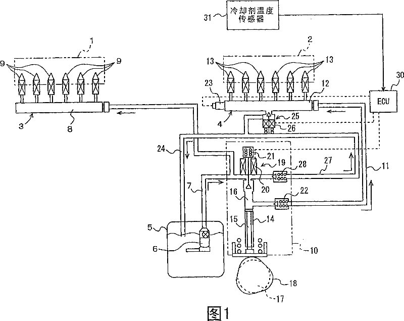
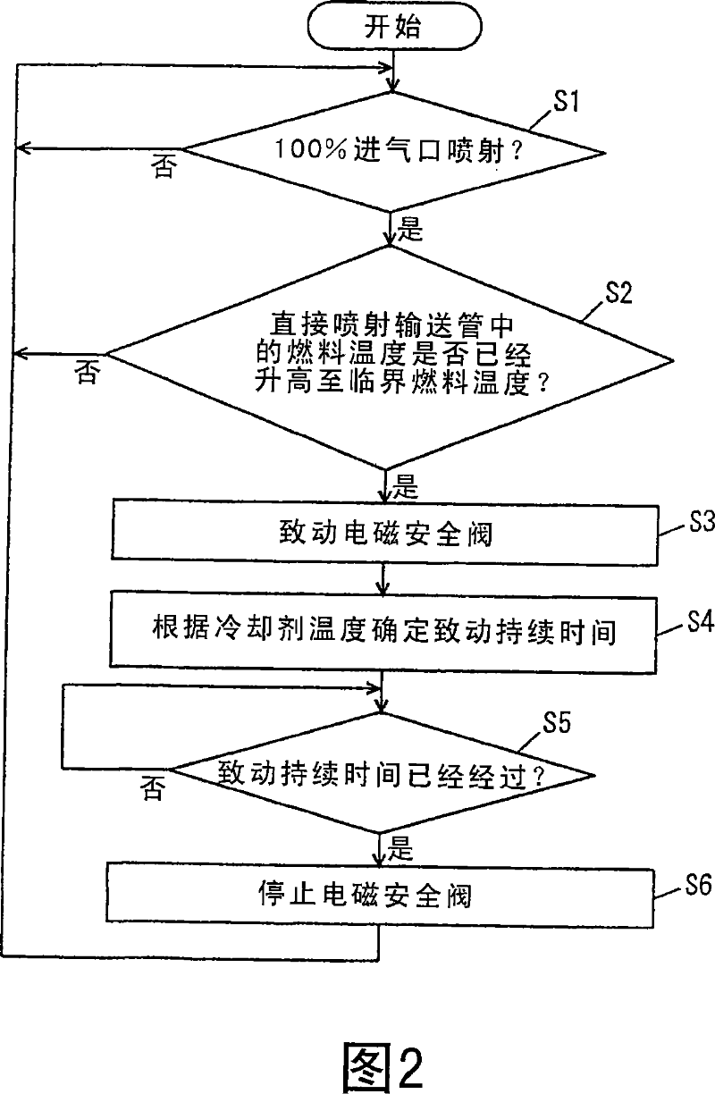
[0060] A fuel injection apparatus for an internal combustion engine according to a first embodiment of the present invention will now be described with reference to FIGS. 1 and 2 . In this embodiment, a fuel injection device for a six-cylinder gasoline engine (as an internal combustion engine) will be described.
[0061] As shown in FIG. 1, the fuel injection apparatus includes a low-pressure fuel supply system 3 that injects fuel into an intake port 1 to provide an air-fuel mixture that is supplied to a combustion chamber 2, and supplies fuel directly into the combustion chamber 2. High pressure fuel supply system 4. The low-pressure fuel supply system 3 and the high-pressure fuel supply system 4 share a low-pressure fuel passage 7 through which fuel (hereinafter referred to as “low-pressure fuel”) is supplied from the fuel tank 5 to the low-pressure fuel pump 6 .
[0062] The low-pressure fuel supply system 3 includes an intake delivery pipe 8 connected to the low-pressure ...
no. 2 example
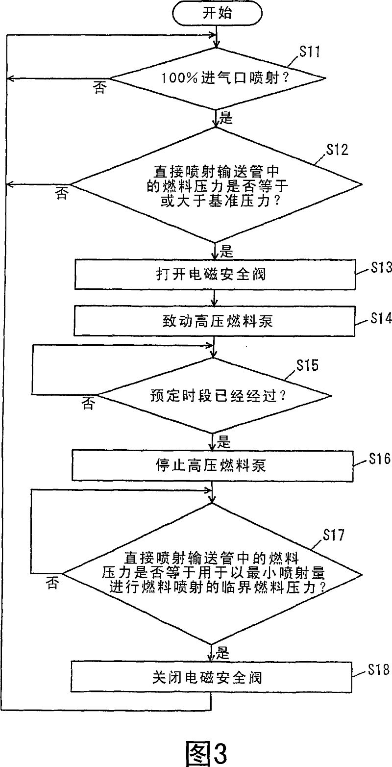
[0109] A second embodiment of the present invention will be described with reference to FIGS. 3 and 4 . The structure of the fuel injection apparatus for an internal combustion engine according to the second embodiment is the same as that shown in FIG. 1 , so description thereof will not be repeated. The control process in the fuel injection device will now be described. FIG. 3 is a flowchart showing a control procedure in the second embodiment, and FIG. 4 is a timing chart showing a control state in the second embodiment.
[0110] The fuel injection apparatus of the second embodiment monitors the fuel pressure inside the in-cylinder injector 13, and when the fuel pressure obtained by monitoring is not lower than the reference pressure P1, it delivers the in-cylinder injection to which the in-cylinder injector 13 is mounted. The fuel in the tube 12 is released outward. A specific control process and control state for releasing fuel will be described with reference to FIGS. 3...
no. 3 example
[0128]A third embodiment of the present invention will now be described. FIG. 5 shows a fuel supply system 90 of the engine controlled by the engine ECU as the control device according to the present embodiment. The engine is a V-shaped eight-cylinder gasoline engine, and has an in-cylinder injector 110 for injecting fuel into each cylinder, and an intake manifold injector for injecting fuel into an intake manifold of each cylinder 120. Note that the present invention is not exclusively applied to the above-mentioned engines, but is also applicable to other types of gasoline engines as well as common rail diesel engines. Furthermore, the number of high-pressure fuel pumps is not limited to one but may be two or more.
[0129] As shown in FIG. 5 , this fuel supply system 90 includes a supply pump 100 provided in the fuel tank for supplying fuel at a low pressure discharge pressure (about 400 kPa corresponding to the pressure of the pressure regulator), a high-pressure fuel pu...
PUM
 Abstract
Description
Claims
Application Information