Driving system of LCD and power supply

A liquid crystal display, power-driven technology, applied in static indicators, instruments, etc., can solve the problems of high cost of power-driven system and high cost of power-driven system of liquid crystal display

Inactive Publication Date: 2007-09-26
INNOCOM TECH SHENZHEN +1
View PDF0 Cites 15 Cited by
  • Summary
  • Abstract
  • Description
  • Claims
  • Application Information

AI Technical Summary

Problems solved by technology

[0010] In order to solve the problem of high cost of the power drive system applied to liquid crystal displays in the prior art, it is necessary to provide a low-cost power drive system
[0011] In addition, in order to solve the problem of high cost of the liquid crystal display due to the high cost of the power drive system in the prior art, it is also necessary to provide a liquid crystal display with a low-cost power drive system

Method used


Image

  • Driving system of LCD and power supply
  • Driving system of LCD and power supply

Examples


Embodiment Construction

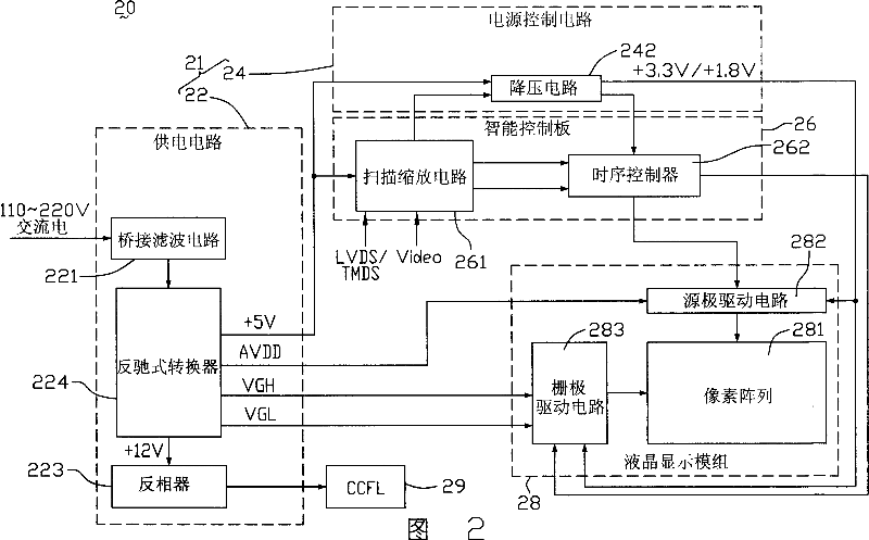
[0017] FIG. 2 is a schematic diagram of the circuit structure of a preferred embodiment of the liquid crystal display of the present invention. The liquid crystal display 20 includes a power drive system 21 , an intelligent control board 26 and a liquid crystal display module 28 . The power drive system 21 provides power for the liquid crystal display 20 . The intelligent control board 26 is used to control the driving circuit of the liquid crystal display module 28 .

[0018] The liquid crystal display module 28 includes a pixel array 281 , a source driving circuit 282 and a gate driving circuit 283 . The source driving circuit 282 and the gate driving circuit 283 jointly drive the pixel array 281 . The gate driving circuit 283 needs to receive the gate working voltage VGH of +15.xV or +24.xV and the gate working voltage VGL of -10.xV or -6.xV, so as to output the scanning signal to the pixel array 281 . The source driving circuit 282 needs to receive the main operating vo...


PUM


Abstract

This invention relates to one power drive system for LCD device, which comprises the following parts as: one power circuit to provide needed voltage for the device; one reverse converter to convert the outer power input voltage alternating electricity into low voltage direct current electricity to multiple path output as the needed work voltage for the LCD device.

Description

【Technical field】 [0001] The invention relates to a power drive system and a liquid crystal display using the power drive system. 【Background technique】 [0002] Liquid crystal displays (liquid crystal displays, LCDs) have been widely used in electronic products such as personal computers, personal digital assistants, and mobile phones due to their advantages such as low power consumption and thinness. [0003] Please refer to FIG. 1 , which is a schematic diagram of a circuit structure of a liquid crystal display in the prior art. The liquid crystal display 10 includes a power drive system 11 , a smart panel (Smart Panel) 16 and a liquid crystal display module 18 . The power drive system 11 provides required power for the LCD 10 . The intelligent control board 16 is used to control the driving circuit of the liquid crystal display module 18 . [0004] The power driving system 11 includes a power supply circuit 12 and a power control circuit 14 . The power supply circuit...

Claims


Application Information

Patent Timeline
Patent Type & Authority Applications(China)
IPC IPC(8): G02F1/133G09G3/36
Inventor 杨坤宪童建凡
Owner INNOCOM TECH SHENZHEN
Why Eureka
Try Eureka