Optical compensation flexure type LCD

A liquid crystal display, optical compensation technology, applied in optics, nonlinear optics, static indicators, etc., can solve problems such as high cost and long initialization time

Inactive Publication Date: 2007-09-26
INNOCOM TECH SHENZHEN +1
View PDF0 Cites 11 Cited by
  • Summary
  • Abstract
  • Description
  • Claims
  • Application Information

AI Technical Summary

Problems solved by technology

[0008] In order to solve the above-mentioned problems of long initialization time and high cost of the optically compensated curved liquid crystal d

Method used


Image

  • Optical compensation flexure type LCD
  • Optical compensation flexure type LCD
  • Optical compensation flexure type LCD

Examples


Embodiment Construction

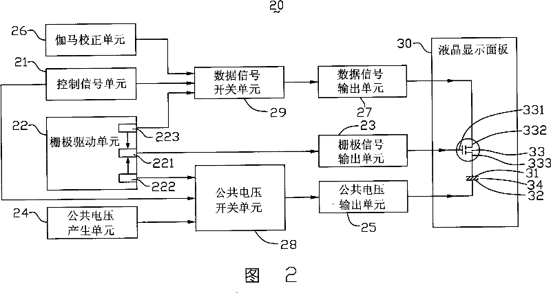
[0017] Please refer to FIG. 2 , which is a schematic diagram of an optically compensated curved liquid crystal display disclosed in the first embodiment of the present invention. The optically compensated curved liquid crystal display 20 includes a control signal unit 21, a gate drive unit 22, a gate signal output unit 23, a common voltage generation unit 24, a common voltage output unit 25, and a gamma correction unit 26 , a data signal output unit 27 , a common voltage switch unit 28 , a data signal switch unit 29 and a liquid crystal display panel 30 . The gamma correction unit 26 is connected to the data signal switch unit 29 , the data signal switch unit 29 is connected to the data signal output unit 27 , and the data signal output unit 27 is connected to the liquid crystal display panel 30 . The common voltage generating unit 24 is connected to the common voltage switch unit 28 , the common voltage switch unit 28 is connected to the common voltage output unit 25 , and th...


PUM


Abstract

This invention relates to one optical compensation curve LCD device, which comprises one LCD panel, one Gamma correction unit, one public voltage generation unit, one grating drive unit and one data signal switch unit, wherein, the grating drive unit comprises one high voltage generation circuit with higher voltage than the correction unit; the LCD panel comprises one pixel electrode and one public electrode; the data signal switch unit is connected to the high voltage generation circuit, correction unit and panel to provide the voltage signals of the Gamma correction unit to the pixel electrode.

Description

【Technical field】 [0001] The present invention relates to a liquid crystal display, in particular to an optically compensated curved liquid crystal display. 【Background technique】 [0002] At present, liquid crystal displays have gradually replaced traditional cathode ray tube (Cathode Ray Tube, CRT) displays used in calculators, and because liquid crystal displays are light, thin, and small, they are very suitable for use in desktop computers, Personal digital assistant (Personal Digital Assistant, PDA), portable phone, TV and various office automation and audio-visual equipment. [0003] In order to increase the viewing angle of the liquid crystal display, an optically compensated bend technology (Optically Compensated Bend, OCB) is proposed in the industry, which realizes self-compensation of the viewing angle by designing the arrangement of liquid crystal molecules. The liquid crystal molecules using OCB technology are in a bent state (Bend Type), and their arrangement ...

Claims


Application Information

Patent Timeline
IPC IPC(8): G02F1/133G09G3/36G02F1/136
Inventor 赖义昶张健仁杨秋莲
Owner INNOCOM TECH SHENZHEN
Why Eureka
Try Eureka