
Touch panel

A touch screen and apex technology, applied in the direction of instruments, electrical digital data processing, input/output process of data processing, etc., can solve the problems of multiple wiring and complicated driving methods, and achieve the effect of simple driving methods

Inactive Publication Date: 2007-09-26
INNOCOM TECH SHENZHEN +1
View PDF0 Cites 3 Cited by
  • Summary
  • Abstract
  • Description
  • Claims
  • Application Information

AI Technical Summary

Problems solved by technology

[0011] In order to solve the problems of many touch screen wirings and complicated driving methods in the prior art, it is necessary to provide a touch screen with less wiring and simple driving methods.

Method used


Image

  • Touch panel
  • Touch panel
  • Touch panel

Examples


Embodiment Construction

[0023] Please refer to FIG. 5 , which is a schematic diagram of the touch screen of the present invention. The touch screen 2 includes: a first input layer 21, which includes an output terminal 211; a second input layer 22, which is stacked with the first input layer 21, and includes first to fourth vertices distributed counterclockwise 233 , 234 , 235 and 236 ; the mesh circuits 23 arranged in rows and columns are arranged between the first to fourth vertices 233 , 234 , 235 and 236 . Wherein, the distance between the first and second vertices 233 , 234 corresponds to the maximum length of the second input layer 22 ; the distance between the first and fourth vertices 233 , 236 corresponds to the maximum width of the second input layer 22 . The second input layer 22 further includes first to eighth diodes 251 , 252 , 253 , 254 , 255 , 256 , 257 and 258 . The mesh circuit 23 includes a plurality of nodes 237 and a plurality of resistors 238, the distance between every two adja...


PUM


Abstract

This invention relates to one touch screen, which comprises overlap set first input layer and second one composed of reverse clock distributed first to fourth top points and one grid circuit and one switch control circuit between first to fourth top points, wherein, the grid circuit further comprises two input ends connected to the switch control circuit; when touching the first input layer, the two input ends are loaded with different levels under the switch control circuit with equal level of first and fourth top points in front half and with third and second ones same and first and second different.

Description

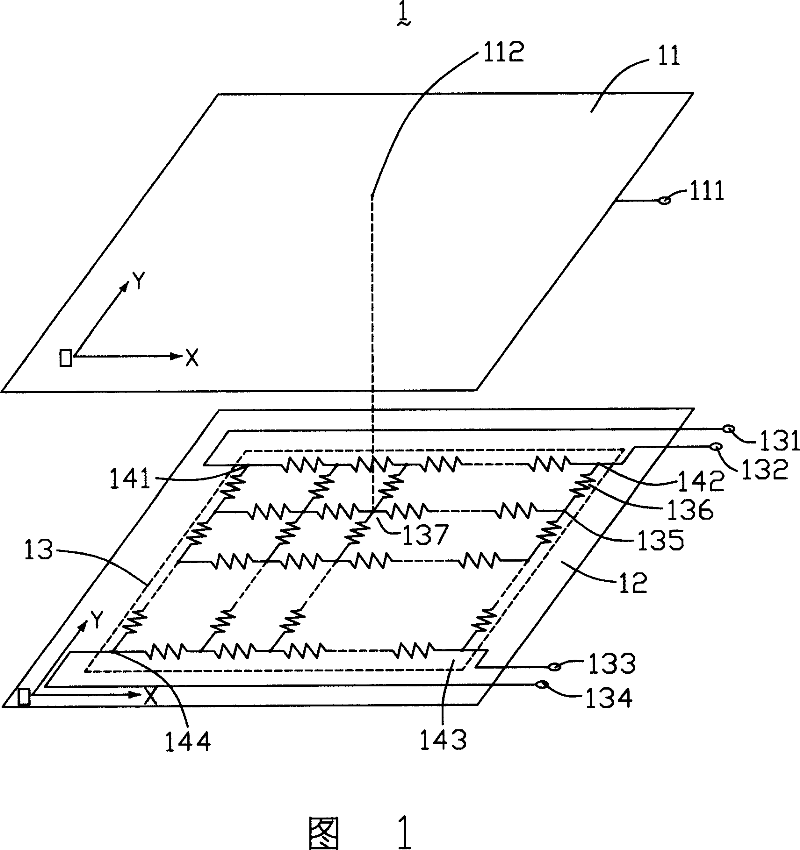
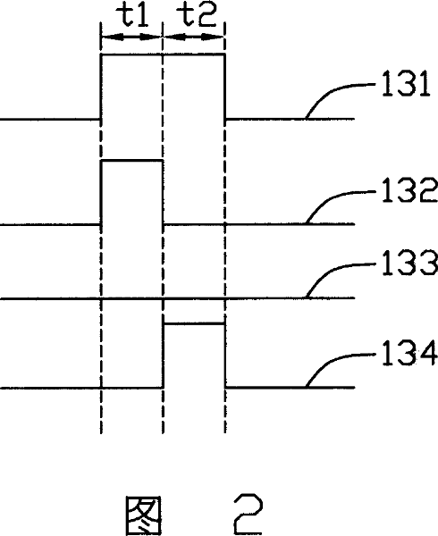
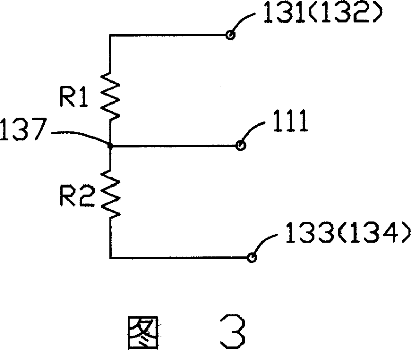
【Technical field】 [0001] The invention relates to a touch screen. 【Background technique】 [0002] Liquid crystal display devices have the advantages of lightness, thinness, and low power consumption, and have been widely used in modern information equipment such as televisions, notebooks, computers, mobile phones, and personal digital assistants. In order to reduce the size of the PDA, the liquid crystal display device used in the PDA is usually combined with a touch screen to omit a key panel or function buttons. Generally speaking, the touch screen generates electrical signals through touch to control the image display of the liquid crystal display device and realize function control. [0003] Please refer to FIG. 1 , which is a schematic diagram of a touch screen in the prior art. The touch screen 1 includes: a first input layer 11, which includes an output terminal 111; a second input layer 12, which is stacked with the first input layer 11, and includes first to fourt...

Claims


Application Information

Patent Timeline
IPC IPC(8): G06F3/041
Inventor 李子升
Owner INNOCOM TECH SHENZHEN
Learn More