Multi-step microactuator

a microactuator and multi-step technology, applied in the direction of electrostatic generator/motor, electrostatic motor, instruments, etc., can solve the problems of high driving voltage, incompatibility with known semiconductor technologies such as mos, cmos, and more complex than digital or discrete control, and achieve the effect of simple driving method

Active Publication Date: 2007-08-09
STEREO DISPLAY
View PDF88 Cites 2 Cited by
  • Summary
  • Abstract
  • Description
  • Claims
  • Application Information

AI Technical Summary

Benefits of technology

[0002] The present invention provides an advanced microactuator for multi-step position control of an object. The microactuator has many advantages for controlling multi-step position such as that the microactutor uses simple driving method, and that single voltage or discretely separated voltage source is used for multi-step position control.

Problems solved by technology

But, it is more complex than the digital or discrete control, and is not compatible with known semiconductor technologies such as MOS, CMOS, etc.
The high driving voltage is another disadvantage in use of the microactuator with continuous displacement actuated by electrostatic force.
But, it is not easy to get a multi-step displacement with simple structure.

Method used


Image

  • Multi-step microactuator
  • Multi-step microactuator
  • Multi-step microactuator

Examples


Embodiment Construction

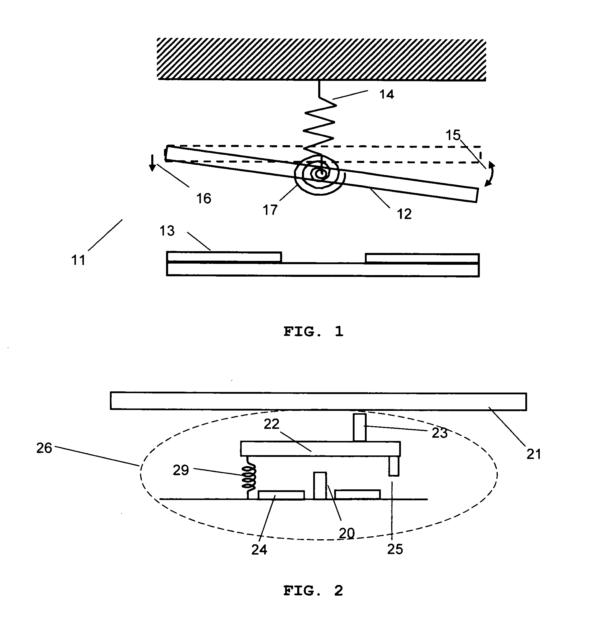
[0018]FIG. 1 shows schematic diagram of a microactuator system 11 giving continuous displacement to the object 12. The object 12 is controlled to have a continuous rotation 15 or translation 16, which is determined by the equilibrium between electrostatic force between the electrode 13 and the object 12 and elastic force of the translational spring 14 and the rotational spring 17. The object 12 is rotated along the hinge supported by the supporting structure. Since the displacement is determined by the equilibrium of the electrostatic and elastic forces, complex analog control with active feedback is required to have a fine control of the motion.

[0019] On the other hand, the multi-step microactuator has simpler control system. Once the motion is defined and programmed in the microactuator, the control is just applying the on / off voltage for desired channel with respect to the desired motion. No feedback is required and the motion is reproducible regardless of the environment.

[0020...


PUM


Abstract

A multi-step microactuator is provided with the multiple supports in a stepper plate to give multi-step displacement to a controlled object. The microactuator has advantages such that multiple motion can be applied to the controlled object and that the object can be controlled in a low driving voltage and that simple motion control is applied by digital controlling and that the degrees of freedom in motion of the object can be chosen by the number of the stepper plate and that only single voltage is needed for driving the micromirror motion. With many advantages, the multi-step microactuator provides a solution to overcome the difficulties in controlling multi-step motion.

Description

BACKGROUND OF THE INVENTION [0001] The microactuators controlled by electrostatic force can be divided into discrete control or digital control and analogy control. Displacement made by analog control is determined at the equilibrium between electrostatic force and elastic force. Therefore, the microactuator with analogy control has continuous displacement through mechanical deformation. But, it is more complex than the digital or discrete control, and is not compatible with known semiconductor technologies such as MOS, CMOS, etc. In addition, the microactuators with continuous displacement actuated by electrostatic force undergo the classical snap-down phenomenon when the electric force exceeds the elastic force of mechanical structure. The snap-down phenomenon limits the displacement range of the microactuator. The high driving voltage is another disadvantage in use of the microactuator with continuous displacement actuated by electrostatic force. To be compatible with IC componen...

Claims


Application Information

Patent Timeline
Patent Type & Authority Applications(United States)
IPC IPC(8): H02N1/00
CPCH02N1/006
Inventor SEO, CHEONG SOOCHO, GYOUNG ILBAEK, SANG HYUNE
Owner STEREO DISPLAY
Why Eureka
Try Eureka