Processor
A processor and arithmetic processing technology, applied in the field of processors, can solve problems such as drawbacks and increased delay, and achieve the effect of high operating frequency and reducing delay
- Summary
- Abstract
- Description
- Claims
- Application Information
AI Technical Summary
Problems solved by technology
Method used
Image

Examples
Embodiment approach 1
[0124] Next, Embodiment 1 of the present invention will be described with reference to the drawings.
[0125] The processor according to Embodiment 1 is characterized in that data conversion such as configuration change, code extension, and zero extension is performed before data is output from the register file to the arithmetic unit, instead of being performed between the memory and the register file.
[0126] Based on the above points of view, the processor according to Embodiment 1 of the present invention will be described.
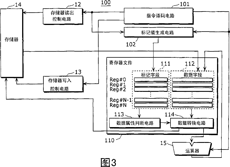
[0127] FIG. 3 is a diagram showing the configuration of a processor according to Embodiment 1. FIG.
[0128] As shown in the figure, the processor 100 includes a memory read control circuit 12 , a memory write control circuit 13 , a memory 14 , and an arithmetic unit 15 . Furthermore, an instruction decoding circuit 101 , a flag value generating circuit 102 , and a register file 110 are provided.
[0129] The instruction decoding circuit 110 output...
Embodiment approach 2
[0190] Next, Embodiment 2 of the present invention will be described with reference to the drawings.
[0191] The processor according to Embodiment 2 is characterized in that before outputting data from the register file to the arithmetic unit, data conversion such as configuration change, code extension, and zero extension is performed inside the register file instead of between the memory and the register file. .
[0192] Based on the above points of view, the processor according to Embodiment 2 will be described.
[0193] In addition, the same code|symbol is attached|subjected to the same component as Embodiment 1, and description is abbreviate|omitted.
[0194] FIG. 9 is a diagram showing the configuration of a processor according to Embodiment 2. FIG.
[0195] As shown in the figure, the processor 200 differs from the processor 100 according to Embodiment 1 in that it includes a register file 210 instead of the register file 110 (see FIG. 3 ).
[0196] Compared with th...
Embodiment approach 3
[0220] Next, Embodiment 3 of the present invention will be described with reference to the drawings.
[0221] The processor according to Embodiment 3 is characterized in that data conversion such as configuration change, code extension, and zero extension is performed inside the arithmetic unit and the memory write control circuit, instead of between the memory and the register file.
[0222] Based on the above points of view, the processor according to Embodiment 3 will be described.
[0223] In addition, the same code|symbol is attached|subjected to the same component as Embodiment 1, and description is abbreviate|omitted.
[0224] FIG. 13 is a diagram showing the configuration of a processor according to Embodiment 3. FIG.
[0225] As shown in the figure, the processor 300 differs from the processor 100 according to Embodiment 1 in the following points (1) to (3) (see FIG. 3 ).
[0226] (1) The register file 310 is provided instead of the register file 110 .
[0227] The...
PUM
 Abstract
Description
Claims
Application Information
 - R&D
- Intellectual Property
- Life Sciences
- Materials
- Tech Scout
- Unparalleled Data Quality
- Higher Quality Content
- 60% Fewer Hallucinations
Browse by: Latest US Patents, China's latest patents, Technical Efficacy Thesaurus, Application Domain, Technology Topic, Popular Technical Reports.
© 2025 PatSnap. All rights reserved.Legal|Privacy policy|Modern Slavery Act Transparency Statement|Sitemap|About US| Contact US: help@patsnap.com