Cooling device with carbon nanaotube coating and method of forming the same

A heat sink, carbon nanotube technology, applied in the direction of carbon nanotube, nanocarbon, nanotechnology, etc., can solve problems such as damage and component failure, and achieve the effect of effective dissipation, improvement of life and performance, and improvement of heat exchange efficiency

Inactive Publication Date: 2007-09-26
SEOUL NAT UNIV R&DB FOUND
View PDF0 Cites 6 Cited by
  • Summary
  • Abstract
  • Description
  • Claims
  • Application Information

AI Technical Summary

Problems solved by technology

Therefore, there is a high possibility of component failure and damage

Method used


Image

  • Cooling device with carbon nanaotube coating and method of forming the same
  • Cooling device with carbon nanaotube coating and method of forming the same
  • Cooling device with carbon nanaotube coating and method of forming the same

Examples


Embodiment Construction

[0025] The present invention will be described more fully hereinafter with reference to the accompanying drawings, in which typical embodiments of the invention are shown. In the drawings, the shapes and thicknesses of layers may be exaggerated for clarity, and the same reference numerals are used to designate the same elements in the various drawings.

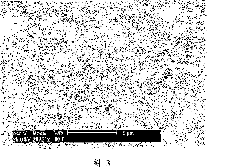
[0026] FIG. 3 is a photograph of a surface of a heat sink, on which carbon nanotubes are adsorbed, according to an exemplary embodiment of the present invention.

[0027] FIG. 3 shows fin surfaces after forming a heat sink including a plurality of fins and performing a dip plating process on the heat sink. In one embodiment, since carbon nanotubes are provided on the surface of the heat sink, compared with the existing heat sink with a planar structure, the heat exchange contact portion can be increased by hundreds to thousands of times. Also, the thermal conductivity of carbon nanotubes is 1800 to 6000 W / mK, and its thermal ...


PUM

PropertyMeasurementUnit
diameteraaaaaaaaaa
lengthaaaaaaaaaa
lengthaaaaaaaaaa

Abstract

Provided are a cooling device coated with carbon nanotubes and method of manufacturing the same. Carbon nanotubes are dispersively coated on a surface of the cooling device that radiates generated by a predetermined apparatus or component through thermal exchange. Thus, a carbon nanotube structure is formed so that the cooling device can improve in a thermal radiation characteristic and become small-sized. As a result, electronic devices can be downscaled and heat generated by a highly integrated electronic circuit chip can be effectively radiated, thus increasing lifetime and performance of an operating circuit.

Description

technical field [0001] The present invention relates to a heat dissipation device and a manufacturing method thereof, more particularly, to a heat dissipation device and a manufacturing method thereof in which a carbon nanotube structure is formed by dip coating. Background technique [0002] As we all know, high power amplifiers (APM) and linear power amplifiers (LPA) for mobile communication relay stations, central processing units (CPUs) for personal computers (PCs), multiple processing units (MPUs) for server-level workstations, and power amplifiers for relay base stations Units (PAUs) are electronic components that generate a lot of heat. When these electronic components operate under destructive loads, their surface temperature rises and they overheat due to the heat generated. Therefore, there is a high possibility of component failure and damage. [0003] In order to prevent malfunction and damage of components, a device for dissipating heat from electronic equipme...

Claims


Application Information

Patent Timeline
Patent Type & Authority Applications(China)
IPC IPC(8): H05K7/20
CPCH05K7/20427B82Y30/00C01B2202/28C01B32/158
Inventor 金龙协李浩荣李承珉成宇镛姜泰俊金曰濬尹壮源延淳昌
Owner SEOUL NAT UNIV R&DB FOUND
Why Eureka
Try Eureka