
Upright-type cleaning appliances

A cleaning device, cleaning technology, used in cleaning equipment, mechanical devices that control suction, carpet sweepers, etc., can solve problems such as danger

Inactive Publication Date: 2007-10-03
VAX LTD
View PDF0 Cites 6 Cited by
  • Summary
  • Abstract
  • Description
  • Claims
  • Application Information

AI Technical Summary

Problems solved by technology

The rotating stirring device then poses a danger to persons near the tipping device, especially children or pets; moreover, clothing, cloth, etc. may become entangled with the stirring device or sucked into the suction hole of the device

Method used


Image

  • Upright-type cleaning appliances

Examples


Embodiment Construction

[0012] The invention will now be described by way of example with reference to the accompanying drawings, which illustrate cleaning devices of the type in which the invention can be practiced.

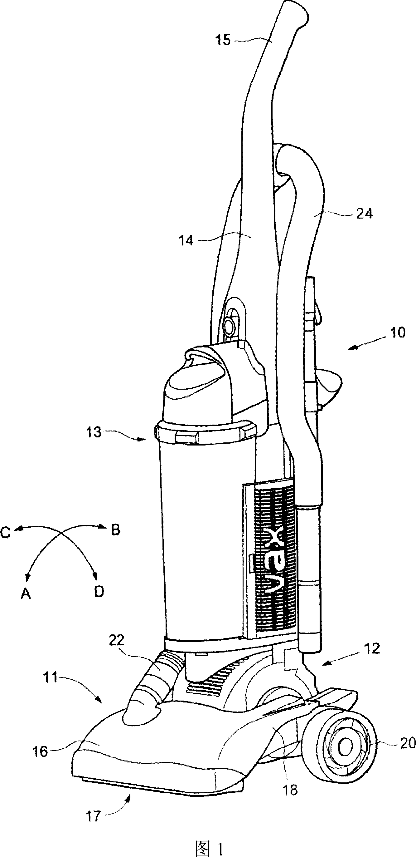
[0013] FIG. 1 shows a cleaning device of an upright vacuum cleaner, which includes a body indicated by 10 and a cleaning head indicated by 11 . The body has a section 12 in which the suction sources of the cleaning machine, ie the motor and the impeller, are located. Above this, the fuselage has a dust separator / collector assembly indicated at 13 . Fuselage section 14 extends above separator / collector assembly 13 and ends in handle 15 . The separator / collector assembly 13 incorporates one or more filters and / or cyclonic separation devices so that, by removing the entire separator / collector assembly or a separate dust-holding portion of the assembly, the airflow drawn by the cleaning machine can be Entrained dust and dirt are separated from this airflow and retained for disposal. All...


PUM


Abstract

A cleaning appliance of the upright type having a cleaning head movable over a floor surface and a body connected to the head, wherein there is provided a means for detecting the attitude of the head and a switch means operable to prevent operation of at least an agitating means, if present, of the appliance if the head assumes an attitude different from a normal operational attitude thereof by more than a predetermined amount.

Description

technical field [0001] The present invention relates to upright cleaning devices. Such a cleaning device may be a vacuum cleaner, or a wet or so-called "suction" type floor cleaning machine in which cleaning liquid is sprayed from a container on the device onto the floor surface, such as a carpet, and then Suction from the floor. Background technique [0002] Such cleaning devices collectively have a cleaning head movable over the floor surface and a body pivotally connected to the cleaning head and extending from the cleaning head to a handle so that the user can Move the head over the floor surface. When the cleaning machine is not in use, the body can usually be placed in a vertical position relative to the head, but when in use, the body can be tilted from a vertical position to an angle suitable for the user. The device has a suction source (motor and impeller) and said head has a suction hole which in operation faces the floor surface so that the air sucked from the...

Claims


Application Information

Patent Timeline
IPC IPC(8): A47L7/00A47L9/00A47L11/29A47L11/32A47L11/40
CPCA47L9/2889A47L5/30A47L9/2805A47L11/40A47L5/28A47L7/0004A47L7/02A47L9/0072
Inventor 克里斯托弗·约翰·图莱蒂
Owner VAX LTD
Learn More