Inhaler for floor

A technology of floor and suction port, applied in the field of suction head, which can solve the problems of increased number of parts, weak rotation force, inability to form suction port, etc., and achieve the effect of easy rotation

Inactive Publication Date: 2007-10-03
SANYO ELECTRIC CO LTD
View PDF1 Cites 7 Cited by
  • Summary
  • Abstract
  • Description
  • Claims
  • Application Information

AI Technical Summary

Problems solved by technology

[0007] However, in this structure, turbines must be installed at both ends of the rotating brush head, which will increase the number of parts, and at the same time, it is necessary to use only a small The external air is used to rotate the turbine, so the rotating force becomes weaker, and good rotating force cannot be obtained when cleaning the surface to be cleaned with high resistance such as pile carpets
In addition, the suction port cannot be formed under the turbine storage chamber, and the suction port becomes smaller relative to the lateral width of the suction head, so there is a problem that dust cannot be completely sucked out.

Method used


Image

  • Inhaler for floor
  • Inhaler for floor
  • Inhaler for floor

Examples


Embodiment Construction

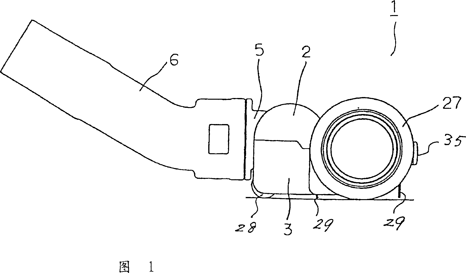
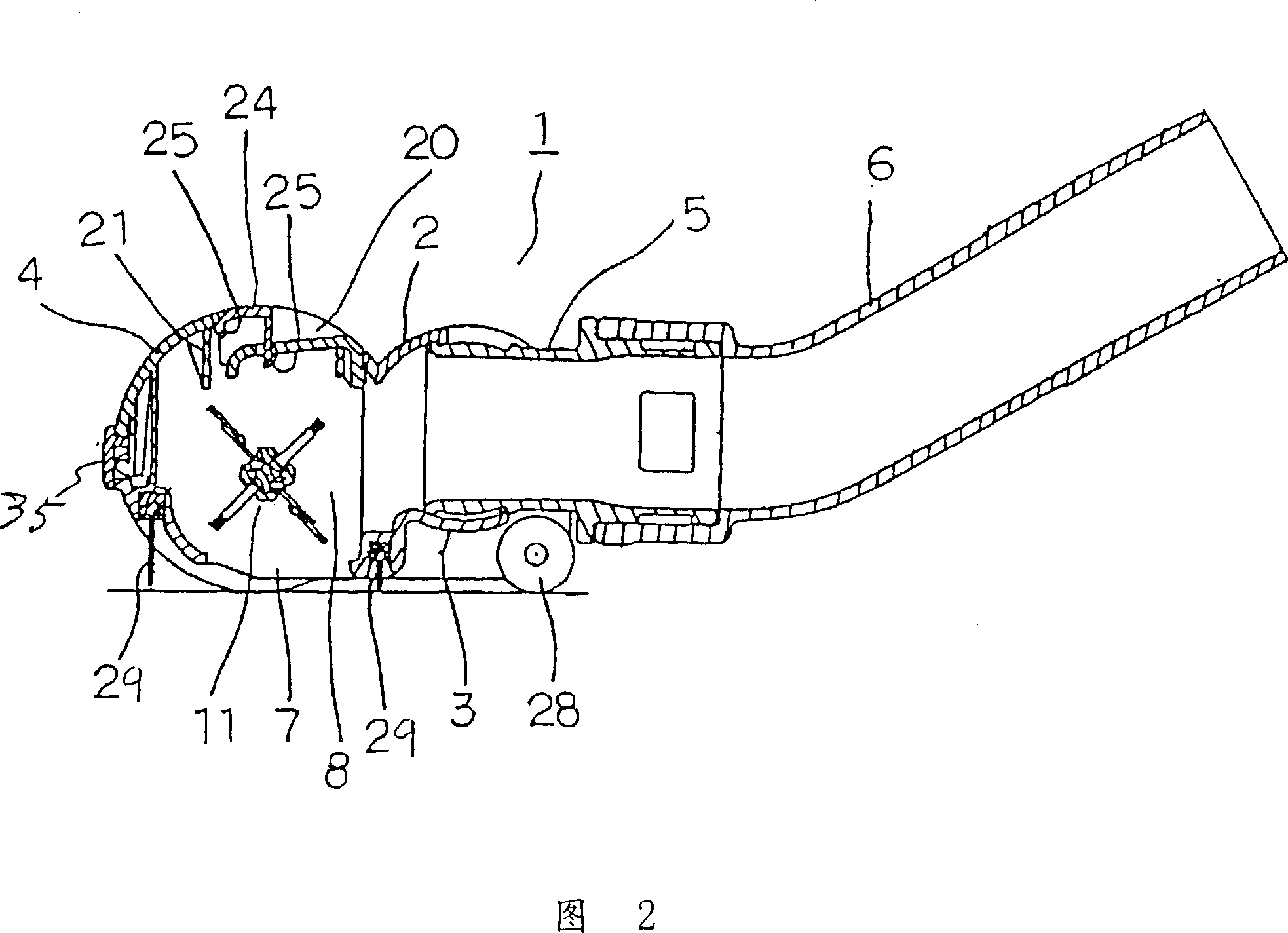
[0097] Referring to Fig. 1 to Fig. 7, it illustrates an implementation state of the present invention. The main body 1 of the suction head of this embodiment includes an upper box body 2, a lower box body 3, a cover body 4 that can be easily loaded and disassembled with the aforementioned upper box body 2 and the lower box body 3, and the upper and lower box bodies 2 and 3 There is a rotating tube 5 , which is movably supported up and down, and a connecting tube 6 , which is rotatably supported on the rotating tube 5 .

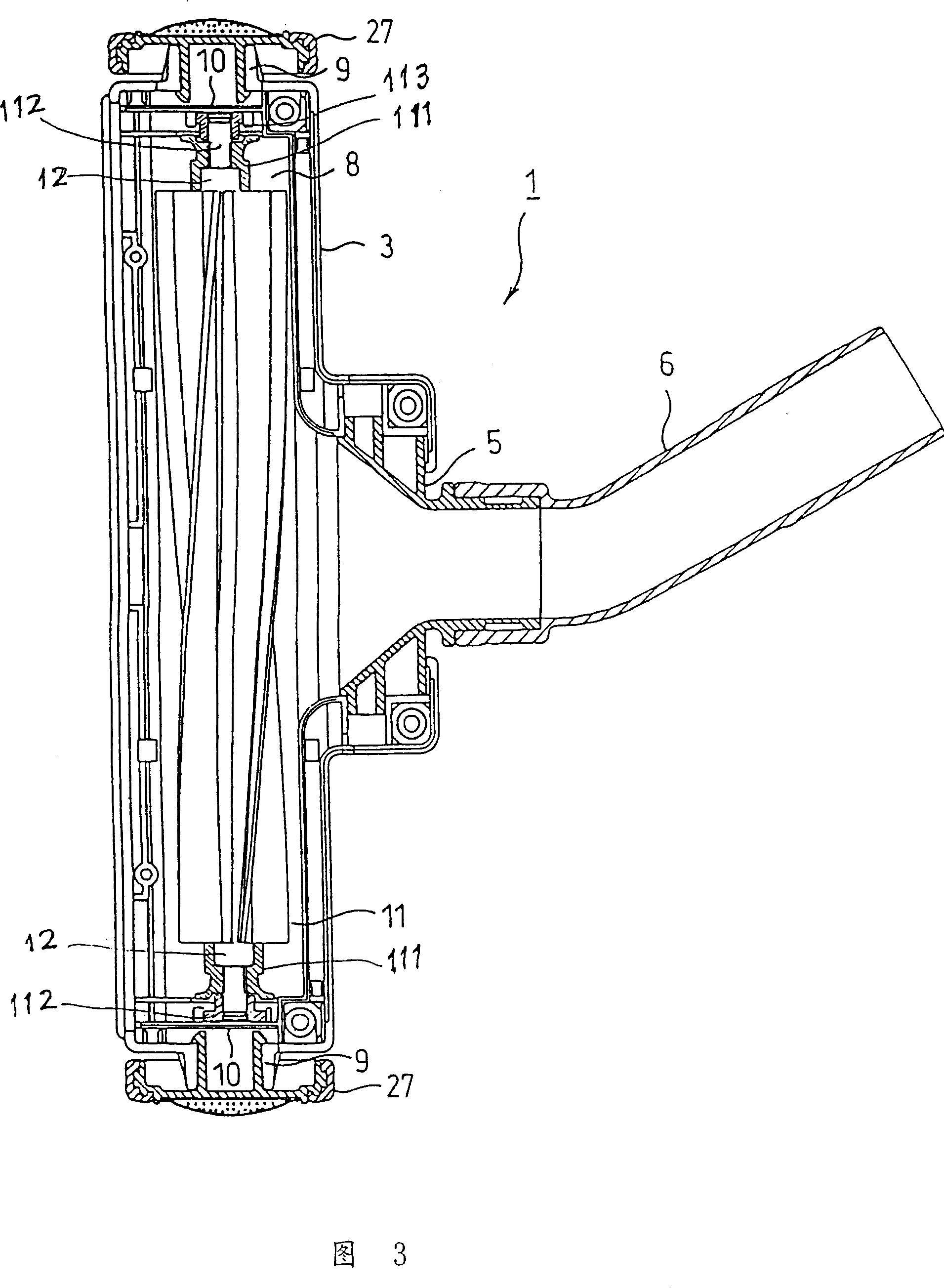
[0098] A suction port 7 is formed at the bottom of the suction head main body 1, and a storage chamber 8 is formed inside.

[0099] Shaft support portions 9 are formed on both sides of the suction head main body 1 to rotatably support wheels 27 described later.

[0100] The partition flange 10 is formed by hanging down the upper and lower boxes 2 and 3 of the suction head main body 1, partitions the shaft support part 9 and the rotating brush head storage cha...


PUM


Abstract

The invention discloses a floor-used inhalation, including: the body of inhalation, the inhaled mouth under the device; rotating brush-received room, formed in the body of the referred inhalation device; rotary brush with leaves, which can be included in the rotating brush-received room rotary, wherein a inhalation path is formed in the clearance of the front and beneath part of the said inhalation device body and the cleaning-surface. The outer air inhaled through the inhalation path is guided to the said leaves under the circumvolving center of the said rotating brush.

Description

[0001] This application is a divisional application. The application date of the corresponding parent application is August 27, 1998. The application number is 98118729.3. The title of the invention is the suction head for electric vacuum cleaners. The applicant is Sanyo Electric Co., Ltd. technical field [0002] The invention relates to a suction head for an electric vacuum cleaner, in particular to an improved suction head connected to the front end of an extension pipe of the electric vacuum cleaner for cleaning floors and other electric vacuum cleaners. Background technique [0003] Conventionally, in such suction heads for electric vacuum cleaners, the rotating brush head is rotatably supported on the suction head main body, and the rotating brush head is rotationally driven by a motor or a turbine. [0004] However, when the rotating brush head is rotationally driven by an electric motor, the electric motor is heavy, poor in operability, complicated in structure, incre...

Claims


Application Information

Patent Timeline
Patent Type & Authority Applications(China)
IPC IPC(8): A47L9/02A47L9/04
Inventor 小林利造会田谦次齐藤和雄杂古昭彦小寺定基佐藤敬一藤吉俊行森好弘
Owner SANYO ELECTRIC CO LTD
Why Eureka
Try Eureka