Gas turbine

a technology of gas turbine and turbine blade, which is applied in the direction of reaction engines, hot gas positive displacement engine plants, non-positive displacement engines, etc., can solve the problems of inability to convert the greater part of high-temperature high-pressure gas spurting from the combustion chamber into a rotational force, the efficiency of the turbine rotational energy conversion is very low, and the gas flow resistance can be reduced. , the effect of improving the efficiency of the turbine rotational energy conversion

Inactive Publication Date: 2013-12-05
KIM KI TAE
View PDF5 Cites 5 Cited by
  • Summary
  • Abstract
  • Description
  • Claims
  • Application Information

AI Technical Summary

Benefits of technology

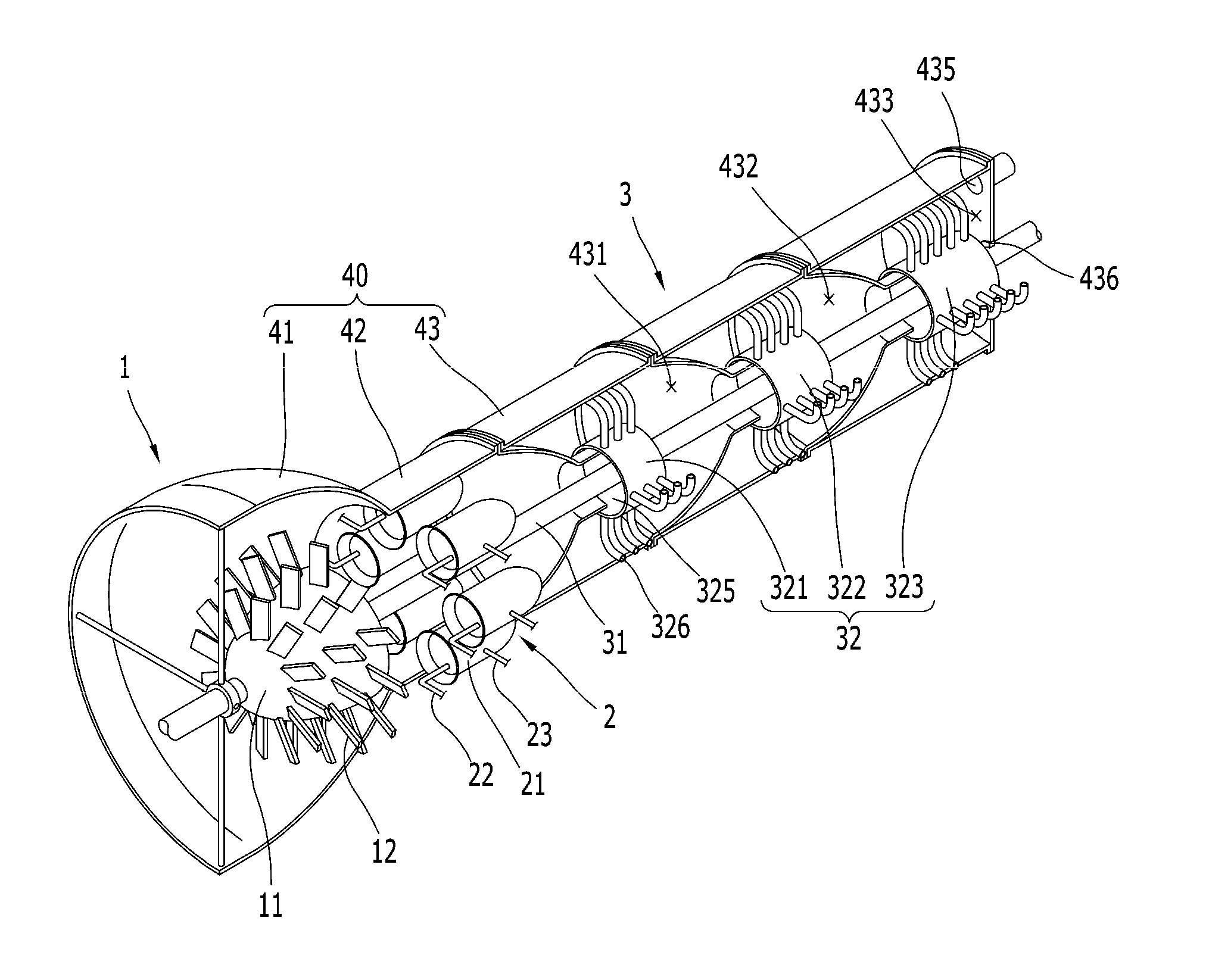
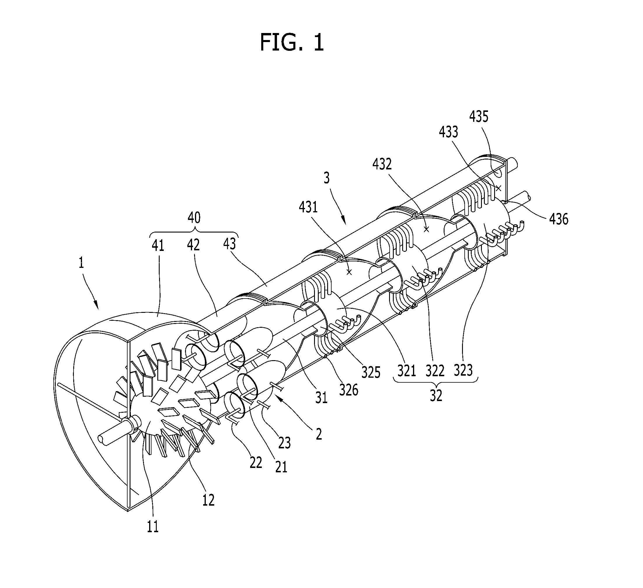
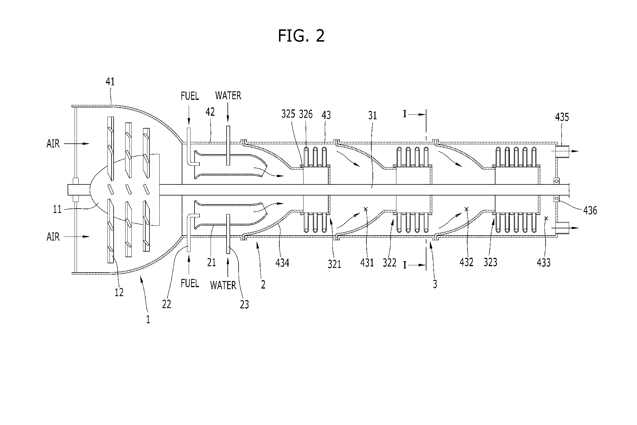
[0014]In a gas turbine according to the present invention, a gas is injected in a circumferential direction so as to rotate a turbine shaft using a repulsive force so that the efficiency of conversion of rotational energy of the turbine can be improved and manufacturing costs can be reduced.
[0015]In addition, a flow resistance to the gas can be reduced, a pressure loss can be prevented, and energy loss can be reduced so as to manufacture an inexpensive turbine having high efficiency.
[0016]In addition, when turbines having capacities different from each other are manufactured, parts can be easily shared with each other, and the eccentric rotation of the turbine shaft can prevented to significantly improve durability.
[0017]Furthermore, an air compression part, a gas expansion part, and a power generation part can be modularized, and fuel and water can be supplied together. Thus, overheating of the gas expansion part can be prevented to remarkably reduce the temperature of an outlet of the gas expansion part and to prevent air from being excessively expanded, and vapor can be generated to reduce the thrust force of an exhaust gas and to improve a rotational force.

Problems solved by technology

Also, when a turbine is used as an engine, such as a tank, the velocity of the tank is very lower than the velocity of the exhaust gas such that the thrust force of the tank is not generated due to the exhaust gas, and the greater part of energy of the exhaust gas wastes.
However, in current gas turbines, it is impossible to convert the greater part of a high-temperature high-pressure gas spurting from a combustion chamber into a rotational force.
Thus, a considerable amount of combustion gas is discharged in a high-temperature high-pressure gas state, and much energy wastes.
Thus, the gas turbine is a very expensive device.
However, since the velocity and direction of a gas that collides with turbine blades are changed, in this consideration, it is very difficult to properly design the shape or angle of the turbine blades in a next row and to arrange several thousands of blades in such a way that the occurrence of turbulence is minimum.
Thus, there is a limitation in manufacturing a turbine having high efficiency.
In addition, in gas turbines according to the related art, the rear turbine is configured in multiple stages, the temperature of the combustion gas is excessively high, the velocity of the discharged combustion gas increases excessively and the discharged combustion gas expands excessively, and the greater part of energy of the exhaust gas is generated as the thrust force in addition to the rotational force.
As a result, in the field where rotational force is required, like in a gas turbine for power generation, the thrust force is a waste of energy that is not conducive to generation of the rotational force.

Method used


Image

  • Gas turbine
  • Gas turbine
  • Gas turbine

Examples


Embodiment Construction

Technical Problem

[0009]The present invention provides a gas turbine that is capable of improving thermal efficiency of a turbine for power generation by converting energy of an exhaust gas into rotational energy at a high rate if possible.

[0010]The present invention also provides a gas turbine that is capable of easily manufacturing a turbine having high efficiency by simplifying factors for determining the momentum caused by a gas.

[0011]The present invention also provides an innovative gas turbine that is capable of forming a turbine in multiple stages and reducing the temperature of a combustion gas so as to convert energy of an exhaust gas into a rotational force and that is capable of improving thermal efficiency of the gas turbine even though the temperature of the exhaust gas is remarkably reduced.

Technical Solution

[0012]According to an aspect of the present invention, there is provided a gas turbine including: a gas expansion part that expands gas; a power generation part tha...


PUM


Abstract

Disclosed is a gas turbine which includes: a gas expansion part that expands gas; a power generation part that generates a rotational force due to the gas expanded by the gas expansion part and has a turbine shaft so as to transfer the rotational force; and an air compression part that is combined with the turbine shaft of the power generation and rotates and compresses air so as to supply compressed air to the gas expansion part. The power generation part generates the rotational force when a nozzle assembly having at least one injection hole so as to inject the gas in a circumferential direction is combined with the turbine shaft and the gas is injected in the circumferential direction via the at least one injection hole.

Description

TECHNICAL FIELD[0001]The present invention relates to a gas turbine that generates a rotational force using a high-pressure operating gas, such as a combustion gas or steam.BACKGROUND ART[0002]In general, gas turbines obtain a rotational force by rotating a turbine disposed as a fan at a rear part of the gas turbine using an injection pressure of a discharged gas and rotates an air compressor disposed at a front part of the gas turbine using a shaft connected to the turbine, thereby supplying compressed air required to combust fuel and to propel a jet engine.[0003]Generally, in jet engines, as the greater part of a thrust force of an airplane is used in a reaction caused by a high-temperature exhaust gas discharged from an engine, uncombusted and remaining air is discharged toward the turbine together with a combustion gas and thus is used to increase a flying velocity. A traditional example thereof is a fan-jet engine used in a large airliner. In the fan-jet engine, about 85% of co...

Claims


Application Information

Patent Timeline
Patent Type & Authority Applications(United States)
IPC IPC(8): F01D1/32
CPCF01D1/32F02C3/305F05D2240/40F02C6/04F02C6/10F02C6/12F02C7/00
Inventor KIM, KI TAE
Owner KIM KI TAE
Why Eureka
Try Eureka