Gas turbine

A gas turbine and turbine shaft technology, applied to gas turbine devices, mechanical equipment, engine components, etc., can solve the problems of waste of propulsion energy, inability to generate rotational force, etc., and achieve the effect of improving eccentric rotation

Inactive Publication Date: 2013-11-27
金其太
View PDF5 Cites 6 Cited by
  • Summary
  • Abstract
  • Description
  • Claims
  • Application Information

AI Technical Summary

Problems solved by technology

So in areas where rotational force is required (similar to gas turbines for power generation), propulsion is a waste of energy that does nothing to generate rotational force

Method used


Image

  • Gas turbine
  • Gas turbine
  • Gas turbine

Examples


Embodiment Construction

[0030] Hereinafter, the gas turbine of the present invention will be explained more fully based on embodiments.

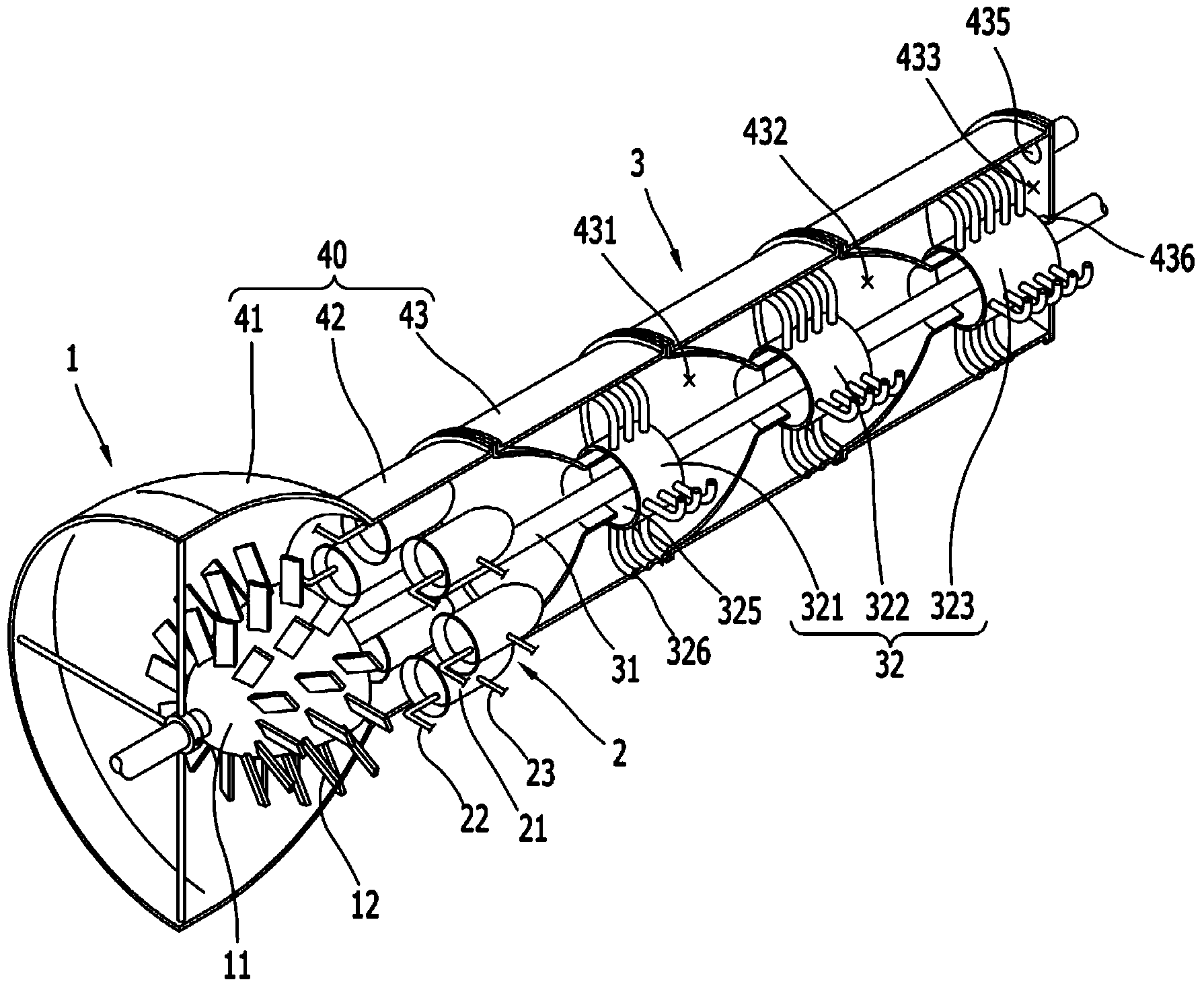
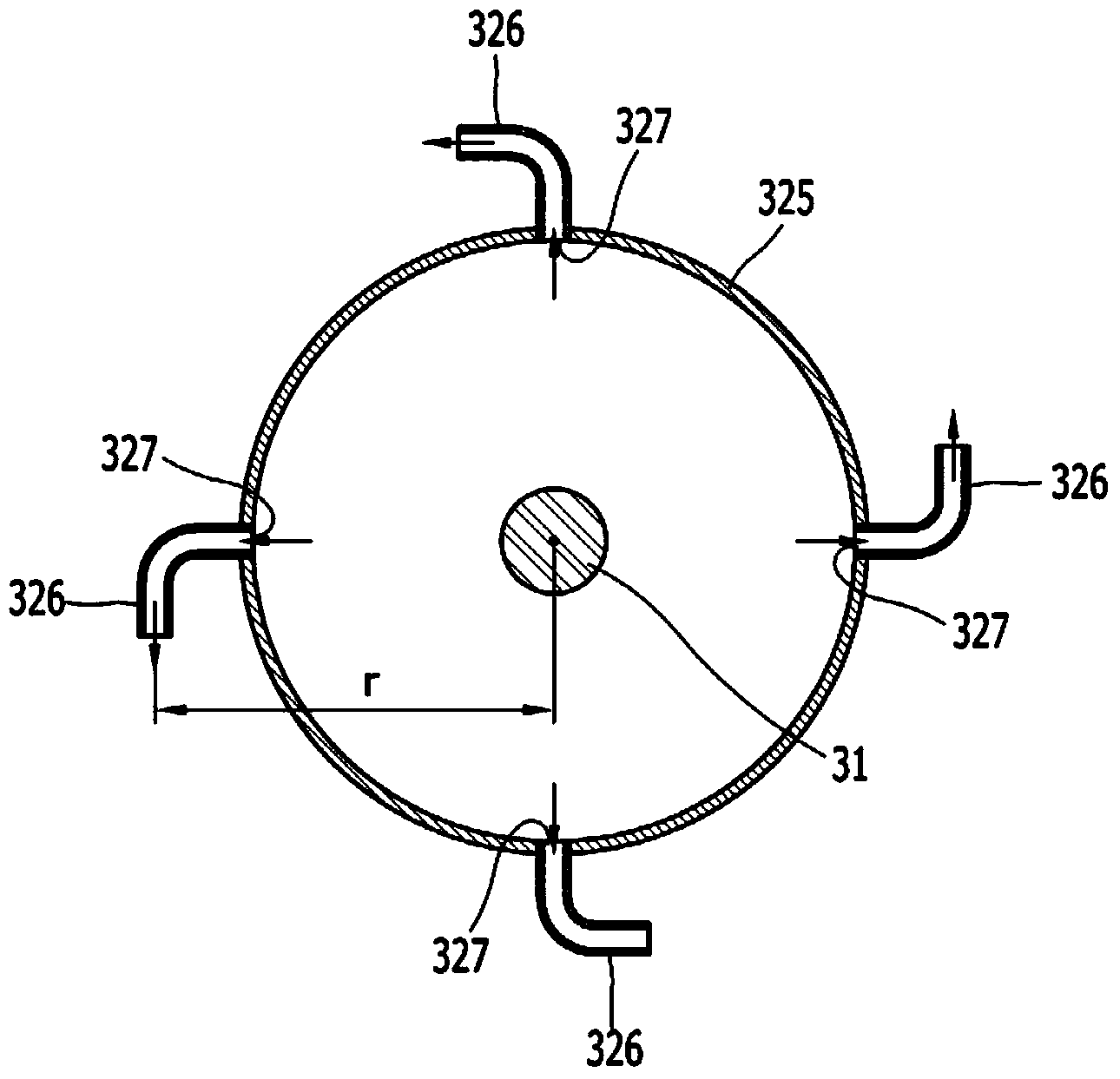
[0031] figure 1 Is a perspective view illustrating the inside of a gas turbine according to an embodiment of the present invention, figure 2 Is illustrated figure 1 A cross-sectional view of the interior of the gas turbine shown in.

[0032] Reference figure 1 with figure 2 , The gas turbine includes: an air compression part 1 for compressing air; a gas expansion part 2 which expands the air compressed by the air compression part 1 to increase the flow rate of the air; and a power generation part 3 when the gas expansion part 2 When the expanded high-temperature and high-pressure air is injected in the circumferential direction, the power generation unit 3 generates rotational force. The air compression part 1, the gas expansion part 2, and the power generation part 3 are sequentially installed inside the housing 40. The air compression part 1 is configured to be comb...


PUM


Abstract

The present invention relates to a gas turbine. According to the present invention, gas may be injected in the circumferential direction in order to rotate the turbine shaft using a repulsive force, thereby improving the efficiency of the conversion of rotational energy of the turbine and reducing manufacturing costs. Also, the flow resistance to the gas may be reduced, pressure leakage may be prevented, and energy loss may be reduced so as to manufacture an inexpensive turbine having high efficiency. In addition, when turbines having capacities different from each other are manufactured, parts may be easily shared with each other, and the eccentric rotation of the turbine shaft may be prevented to significantly improve durability. Also, an air compression part, a gas expansion part, and a power generation part may be modularized, and fuel and water may be supplied together. Thus, overheating of the gas expansion part may be prevented to prevent air from being excessively expanded, and vapor may be generated to improve rotational force in addition to the impellent power of the turbine. Also, the gas turbine may be manufactured using a relatively inexpensive metal material instead of expensive high temperature ablative materials in order to reduce manufacturing costs.

Description

Technical field [0001] The present invention relates to a gas turbine that uses high-pressure working gas such as combustion gas or steam to generate rotational force. Background technique [0002] Generally, a gas turbine obtains rotational force by using the injection pressure of exhaust gas to rotate a turbine (the turbine is arranged as a fan at the rear of the gas turbine), and uses a shaft connected to the turbine to make it installed in front of the gas turbine. The air compressor at the unit rotates, thereby providing the compressed air needed to burn fuel and propel the jet engine. [0003] Generally, in a jet engine, a larger part of the propulsion force of the aircraft is the reaction force caused by the high-temperature exhaust gas discharged from the engine, so the unburned and remaining air is discharged to the turbine together with the combustion gas, thereby being Used to increase flight speed. A typical example of this situation is the fan-jet engine used in larg...

Claims


Application Information

Patent Timeline
Patent Type & Authority Applications(China)
IPC IPC(8): F02C6/04F01D9/02F01D9/06F02C7/00
CPCF05D2240/40F01D1/32F02C3/305F02C6/04F02C6/10F02C6/12F02C7/00
Inventor 金其太
Owner 金其太
Why Eureka
Try Eureka