Tubular case

一种收纳容器、外壳的技术,应用在封盖、手动装置、印刷等方向,能够解决无法减轻嵌合解除操作力、距离增大、无法确保等问题,达到稳定维持盖安装状态、确保旋转角度的效果

Inactive Publication Date: 2007-10-03
KOKUYO S&T CO LTD
View PDF2 Cites 0 Cited by
  • Summary
  • Abstract
  • Description
  • Claims
  • Application Information

AI Technical Summary

Problems solved by technology

[0006] However, in the structure described in Patent Document 1, the support rod is substantially U-shaped, and the distance between the cam and the above-mentioned rotation center is extremely short, that is, the force point for applying the force to release the cap from the mated state is very close to the fulcrum. , so there may be the following disadvantages: the operation force required to release the fitting cannot be reduced, and at the same time, a large cover displacement cannot be ensured.
In addition, when reducing the operating force, it is necessary to increase the distance between the above-mentioned rotation center corresponding to the fulcrum and the point of action as the point of application of the operating force, thereby necessitating that the point of action of the support rod be aligned in the radial direction of the housing. Such inappropriate situations are greatly highlighted on the
Furthermore, since the point of action protrudes greatly in this way, the fitting of the cover may be unintentionally released.

Method used


Image

  • Tubular case
  • Tubular case
  • Tubular case

Examples


Embodiment Construction

[0047] Hereinafter, an embodiment in which the present invention is used as a storage container using a stick-shaped solid paste as a storage target will be described with reference to the drawings.

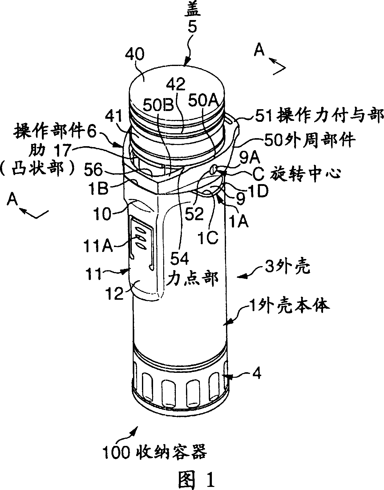
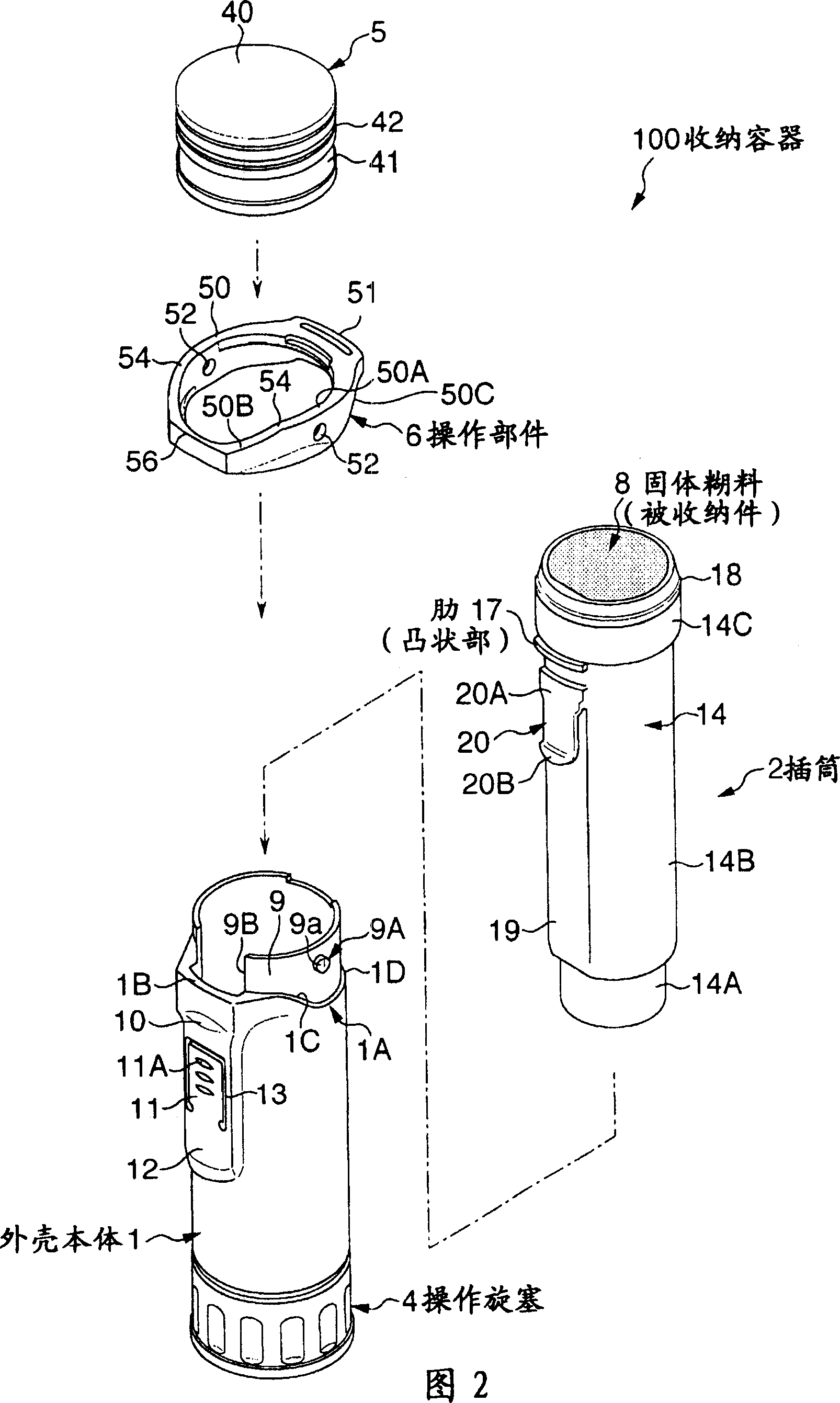
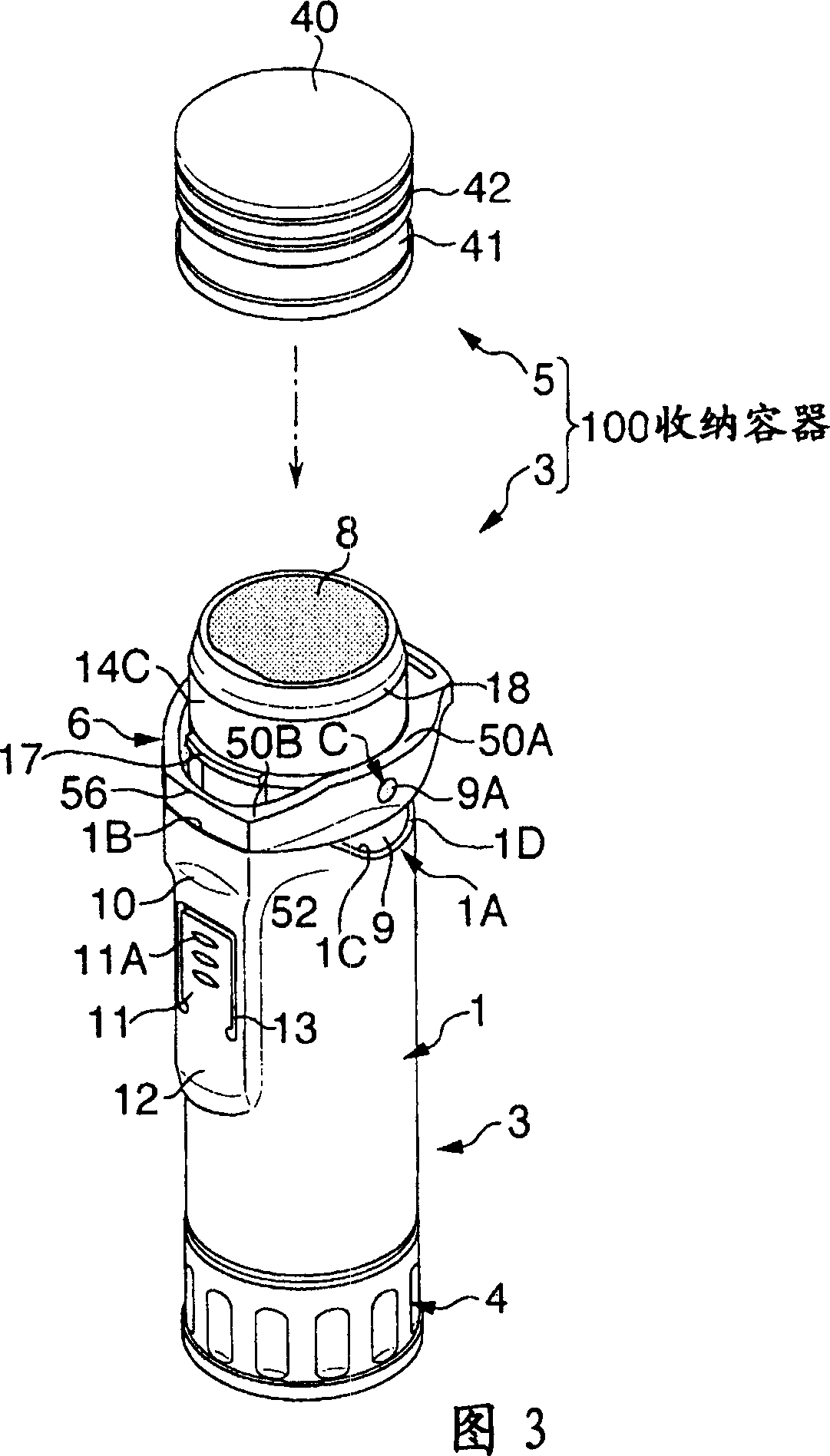
[0048] FIG. 1 shows a schematic perspective view of a storage container according to this embodiment, and FIG. 2 shows an exploded perspective view thereof. In addition, in FIG. 3, the schematic perspective view of the storage container in the state which removed the cover is shown. In these figures, the storage container 100 includes: a housing 3 including a housing body 1 and an insert 2 (see FIG. 2 ) housed in the housing body 1 , and a housing 3 rotatably mounted on the lower end of the housing body 1 in the drawings. The operation cock 4, the cap 5 fitted to the upper end portion of the insertion sleeve 2 in the drawing, and the operation member 6 for releasing the fitting of the cap 5 and the insertion sleeve 2.

[0049]The above-mentioned casing body 1, as shown in FIG. 2...


PUM


Abstract

A cylindrical case 3 receives a stick of solid glue 8 as an item to be received in a reciprocating manner so as to come out and retract through an opening of the case 3. A cap 5 is arranged to engage with the opening of the case 3. Engagement release of the cap 5 is carried out by rotating an operating member 6. The operating member 6 includes a peripheral member 50 and an operating force imparting portion 51 continuous with the peripheral member 50 mounted on an upper portion of the case 3. When the operating force imparting portion 51 is pressed downward, force apply points 54 formed at a side opposite of the operating force imparting portion 51 impart a push-up force to the cap 5 thereby releasing the cap 5 from the engagement.

Description

technical field [0001] The present invention relates to a storage container in which, for example, a stick-shaped solid paste is used as an object to be accommodated, and it is arranged so that it can go in and out from the opening of the casing. storage container below. Background technique [0002] Conventionally, there is known a storage container in which a solid paste is accommodated as an object to be accommodated in a housing having a substantially cylindrical appearance, and the solid paste is provided so as to be able to be moved with respect to an opening provided on one end side of the housing. haunt. This storage container is provided with a cover for closing the opening of the case, and the cover has a structure that snap fits into the outer periphery of the case. [0003] This kind of cover, through the above-mentioned fitting structure, can prevent inadvertently falling off from the casing, but on the other hand, since it is formed in a relatively short cyli...

Claims


Application Information

Patent Timeline
Patent Type & Authority Applications(China)
IPC IPC(8): B65D83/00B65D43/02B65D43/26B43M17/00B43M99/00
CPCB65D83/0011B43M11/00B65D83/00
Inventor 小林彰吾岛秀人
Owner KOKUYO S&T CO LTD
Why Eureka
Try Eureka