Floating sealer and the compressor therewith
A floating seal and compressor technology, applied in the field of scroll compressors, can solve the problems of complex structure, difficult assembly and high cost of floating seal devices, and achieve the effect of simple structure, low cost and high compression efficiency
- Summary
- Abstract
- Description
- Claims
- Application Information
AI Technical Summary
Problems solved by technology
Method used
Image

Examples
Embodiment 1
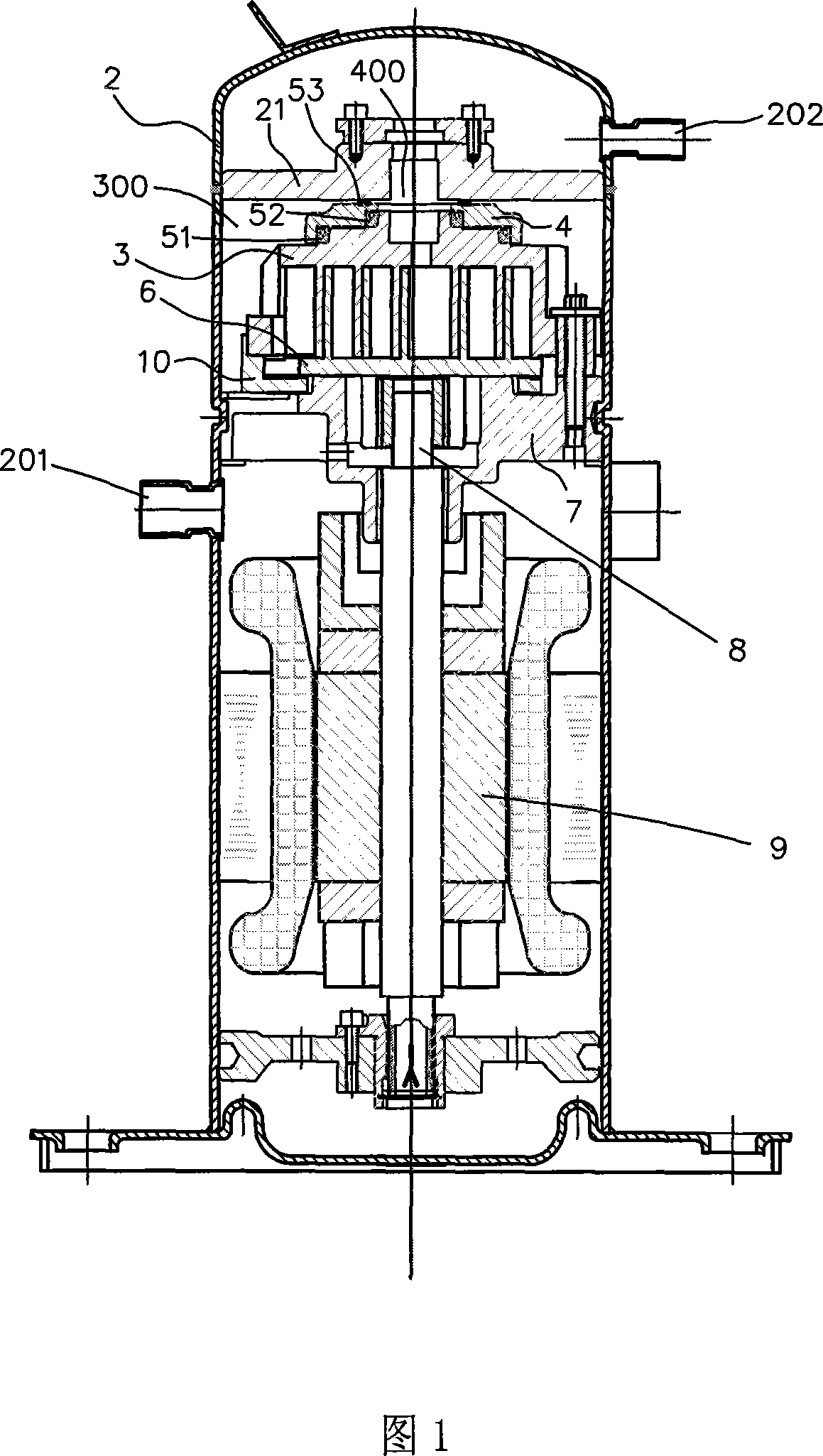
[0033] Please refer to Fig. 1, the compressor provided by this embodiment includes a sealed casing 2, a high and low pressure partition plate 21 is arranged inside the sealed casing 2, and a fixed scroll 3 is arranged below the high and low pressure partition plate 21 and cooperates with the fixed scroll 3 In order to realize the sealing cover 4 and the sealing rings 51, 52, 53 with the floating sealing function, the movable scroll 6 installed opposite to the fixed scroll 3 is arranged under the fixed scroll 3, so that the two scrolls are in a suction pressure zone 300 and a discharge pressure zone A compression chamber with gradually changing volume is formed between 400. A bearing seat 7 is arranged in the sealed casing 2 to install the fixed scroll 3 and make it have limited axial movement relative to the movable scroll 6. The bottom of the movable scroll 6 is in contact with the movable scroll. The crankshaft 8 cooperates with the motor assembly 9. The crankshaft 8 and the ...
Embodiment 2
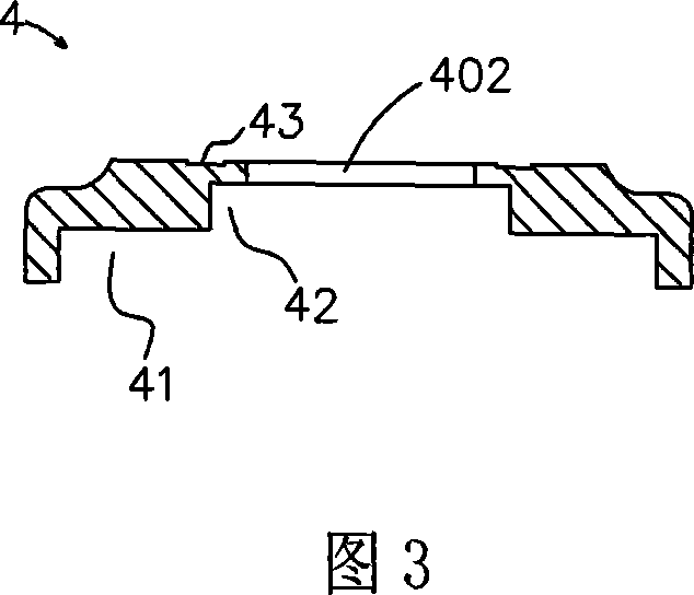
[0043] Please refer to Fig. 5, the difference between the compressor with floating sealing device provided by the second embodiment and the first embodiment is that the top end of the sealing cover 4 and the high and low pressure partition plate are used to cooperate with the sealing mechanism for separating the suction pressure zone and the discharge pressure zone Different, in the first embodiment, the groove 43 cooperates with the structure of the sealing ring 53. In the second embodiment, the closed boss 44 integrally formed at the top of the sealing cover 4 and the sealing gasket 211 provided at the bottom of the high and low pressure partition plate are used. . This embodiment can achieve the same purpose and function as the first embodiment.
Embodiment 3
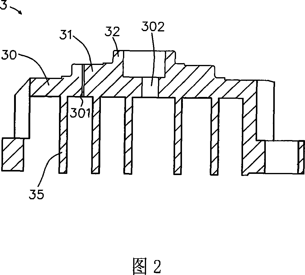
[0045] Please refer to Fig. 6. The difference between Embodiment 3 and Embodiment 2 is that the compressor with floating sealing device is provided in that the boss on the top of the end plate of fixed scroll 3 is a first-order boss, which is marked as 310 in Fig. The groove provided on the bottom of the cover 4 is correspondingly a first-order groove, and the upper end of the boss 310 is partially embedded in the groove, so that the medium-pressure chamber 100 is formed between the top surface of the boss 310 and the bottom surface of the groove. The first seal is arranged between the outer side wall of the boss 310 and the outer side wall of the groove, so as to isolate the medium pressure chamber 100 from the suction pressure area 300, and the second seal is arranged on the inner side wall of the boss 310 and the groove Between the inner side walls, thereby isolating the medium pressure chamber 100 from the discharge pressure area 400, the boss 44 provided on the top end of ...
PUM
 Abstract
Description
Claims
Application Information
 - Generate Ideas
- Intellectual Property
- Life Sciences
- Materials
- Tech Scout
- Unparalleled Data Quality
- Higher Quality Content
- 60% Fewer Hallucinations
Browse by: Latest US Patents, China's latest patents, Technical Efficacy Thesaurus, Application Domain, Technology Topic, Popular Technical Reports.
© 2025 PatSnap. All rights reserved.Legal|Privacy policy|Modern Slavery Act Transparency Statement|Sitemap|About US| Contact US: help@patsnap.com