
Zoom lens device

A zoom lens and lens retention technology, applied in installation, optics, instruments, etc., can solve the problems of large torque, difficulty in smooth movement of cam push rod, etc., and achieve the effect of reducing the diameter of the cylinder

Inactive Publication Date: 2007-10-03
FUJI PHOTO OPTICAL CO LTD
View PDF1 Cites 24 Cited by
  • Summary
  • Abstract
  • Description
  • Claims
  • Application Information

AI Technical Summary

Problems solved by technology

In this case, if the cylinder diameter of the cam cylinder is small, the angle of the cam surface with respect to the direction of rotation becomes steeply inclined, so a large torque is required to rotate the cam cylinder, and it becomes difficult to move the cam push rod smoothly.

Method used


Image

  • Zoom lens device
  • Zoom lens device
  • Zoom lens device

Examples


Embodiment Construction

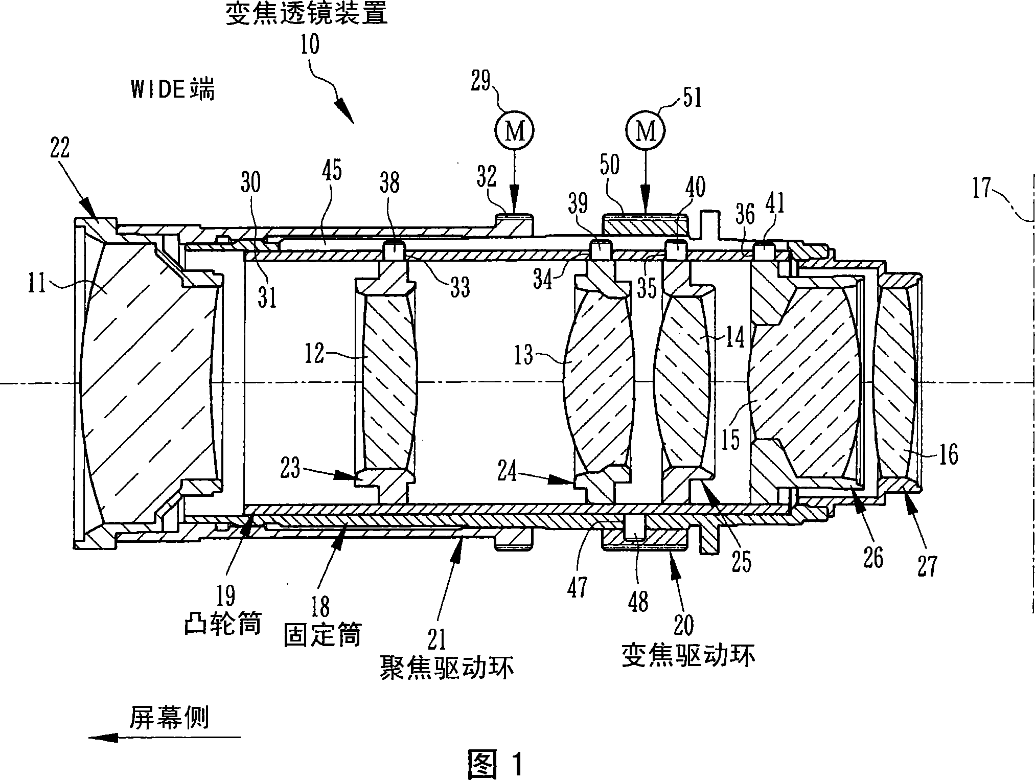
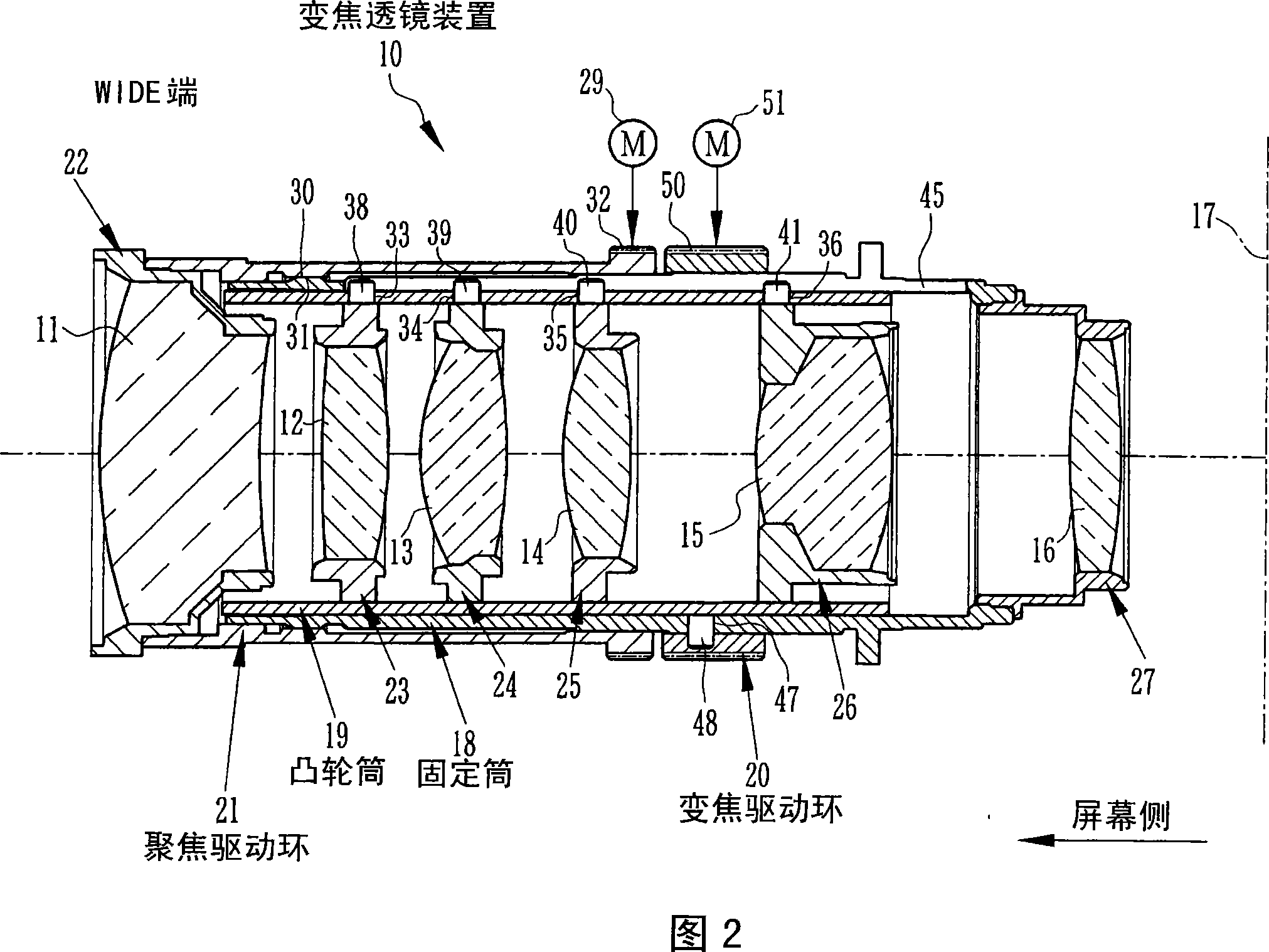
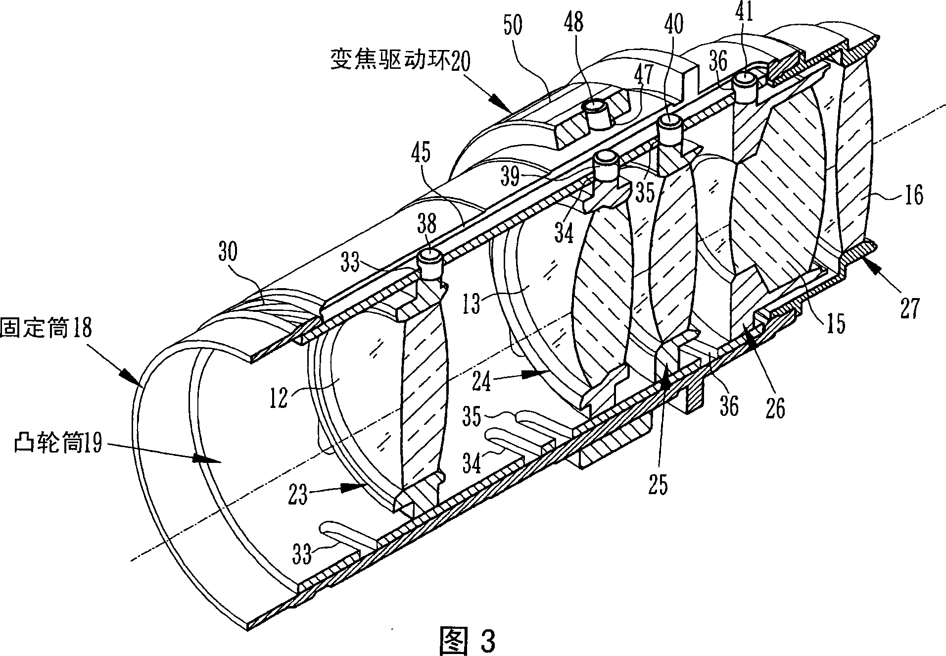
[0016] The zoom lens device 10 is a device used in a projector, and includes first to sixth lens groups 11 to 16 in order from the screen side (objective lens side) as shown in FIGS. 1 to 3 . During focusing, the first lens group 11 as a front lens moves in the direction of the optical axis, and during zooming, the second to fifth lens groups 12 to 15 move in the direction of the optical axis, respectively. In addition, the sixth lens group 16 is fixed. In addition, reference numeral 17 is a surface on which a document for projection etc. is placed, for example, in a liquid crystal projector, it is a surface on which a liquid crystal panel is placed.

[0017] The lens barrel of the zoom lens device 10 is composed of a fixed barrel 18, a cam barrel 19, a zoom drive ring 20, a focus drive ring 21, and first to sixth lens holding frames 22 to 27 for respectively holding the first to sixth lens groups. constitute. In the fixed barrel 18, the sixth lens holding frame 27 is fixed ...


PUM


Abstract

A cam barrel 19 rotates in one way in varying a power to move four lens holding frames in the same direction by displacements of four cam openings 33 to 36 . Cam barrel cam followers 48 are provided on an outer periphery of the cam barrel 19 . The cam barrel cam followers 48 are passed through cam barrel cam openings 47 provided to a fixed barrel being arranged on an outer periphery of the cam barrel 19 , and engage with a power variation driving ring arranged on an outer periphery of the fixed barrel. The power variation driving ring is used to rotate the cam barrel 19 and move respective lens holding frames. Since the cam barrel cam followers 48 engage with the cam barrel cam openings 47 , the cam barrel 19 is moved according to displacements of the cam barrel cam openings 47 while holding respective lens holding frames. So a cam can be formed on small-diameter cam drum via assuasive inclined.

Description

technical field [0001] The present invention relates to a zoom lens device in which a plurality of lens holding frames are simultaneously moved in the direction of an optical axis by rotating a cam cylinder relative to a fixed cylinder. Background technique [0002] As a conventional zoom lens device, it is known to utilize a cam mechanism that, for example, rotates a cam tube relative to a fixed tube during zooming and guides a cam follower (cam follower) provided on a lens holding frame to a cam follower arranged in a spiral shape. At the intersection of the cam surface of the cam cylinder and the linear guide surface provided on the fixed cylinder, the lens group held by the lens holding frame is moved in the optical axis direction (Patent Document 1). [0003] In recent years, zoom lens devices have been increasingly required to increase the magnification of the zoom magnification and to reduce the size thereof. In order to realize high magnification, it is necessary to...

Claims


Application Information

Patent Timeline
Patent Type & Authority Applications(China)
IPC IPC(8): G02B7/04G02B7/10
CPCG02B7/10G02B7/102
Inventor 松本智神垣哲生
Owner FUJI PHOTO OPTICAL CO LTD
Learn More