
Rolling stand for producing rolled strip

a technology of rolling stand and rolling plate, which is applied in the direction of manufacturing tools, counter-pressure devices, profile control devices, etc., can solve the problems of losing the major advantages of rolls contoured in such a way, and the edges or quarters are not uniform,

Inactive Publication Date: 2008-01-08
PRIMETALS TECH AUSTRIA GMBH
View PDF11 Cites 4 Cited by
  • Summary
  • Abstract
  • Description
  • Claims
  • Application Information

AI Technical Summary

Benefits of technology

[0005]The object of the present invention is to provide a further advantageous solution for a rolling stand in which the form of the roll gap, i.e. the thickness profile of the roll gap over the active roll barrel length, can be varied by axial displacement of the rolls provided with a roll barrel contour in relation to one another in such a way that a strip which meets the highest quality requirements, is planar and free from undulations is obtained.
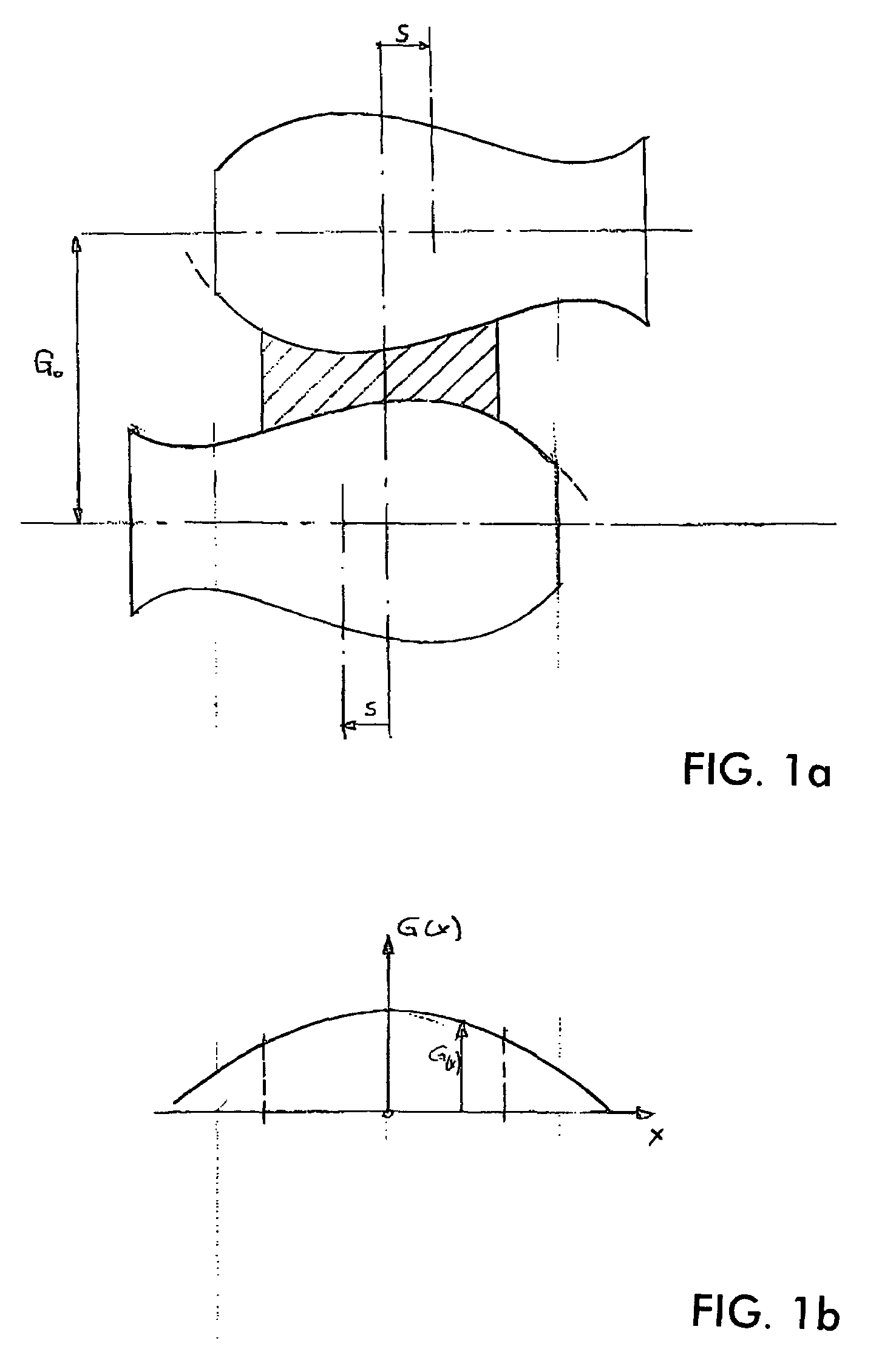
[0021]By varying the contour angle φ, which relates to half the camber reference length, the current roll contour, and consequently the profile of the roll gap, can be influenced without changing the equivalent cambers of the rolls. The positive effect with regard to avoidance of the formation of undulations in the quarter area is obtained, because an increase in the contour angle leads to a decrease in the roll barrel diameter in the region between the edge of the roll and the center of the roll, whereby ultimately a smaller rolling deformation occurs in this region that is critical for the formation of undulations in the quarter area.
[0028]By inserting the linear element B*(x+c) into the equation for the barrel contour, tilting of the sine function is made possible and, by suitable choice of the coefficient (B), minimizing of the differences in diameter along the barrel contour is achieved. The minimizing of the differences in diameter along the effective length of the roll barrel achieved by the tilted sine function leads at the same time to a reduction in the axial forces dissipated into the roll supporting bearings during the rolling operation. In the case of rolling stands which are equipped with backup rolls in addition to the work rolls provided with a barrel contour, the optimization of the tilting coefficient leads to a reduction in the maximum local contact pressures on the backup rolls, or generally to a more uniform distribution of forces on the neighbouring rolls. The tilting coefficient (B) consequently brings about a smoothing of the contour profile on the roll barrel and of the distribution of forces. Consequently, although the introduction of a tilting coefficient into the contour equation of the roll barrels favorably influences the loading to which the rolls and bearings of the rolling stand are subjected, it does not exhibit any fundamental influence on the roll gap geometry, as shown by the comparison of the two roll gap equations based on a sine function and a tilted sine function for the roll barrel contour.
[0031]There is an approximation to minimizing the axial forces to be dissipated into the roll supporting bearings when the tilting coefficient (B) in the equation for the barrel contour of each roll is chosen such that the maximum difference in diameter of the barrel contours within the camber reference length or the barrel length is at a minimum.
[0032]Influencing the rolls in such a way as to improve the quality of the strip can be obtained if further actuators, influencing the barrel contour at least in certain portions, are additionally positioned in the rolling stand in operative connection with the work rolls and / or backup rolls and / or intermediate rolls, such as for example work roll cooling or zone cooling. Corresponding effects may also be realized by roll bending devices or by heating devices which can be zonally switched on.

Problems solved by technology

In EP-B 294 544 it is pointed out that the parabolic bending determined essentially by quadratic components can be compensated by axially displaceable rolls with the described roll contour, but excessive stretching in the edge areas or in the quarter areas of the rolled strip can lead to undulations in the edge or quarter area.
Although these disadvantages could be overcome with additional roll bending devices, expediently in combination with zone cooling, major advantages of rolls contoured in such a way would be lost again as a result.

Method used


Image

  • Rolling stand for producing rolled strip
  • Rolling stand for producing rolled strip
  • Rolling stand for producing rolled strip

Examples


Embodiment Construction

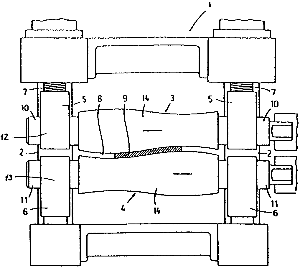
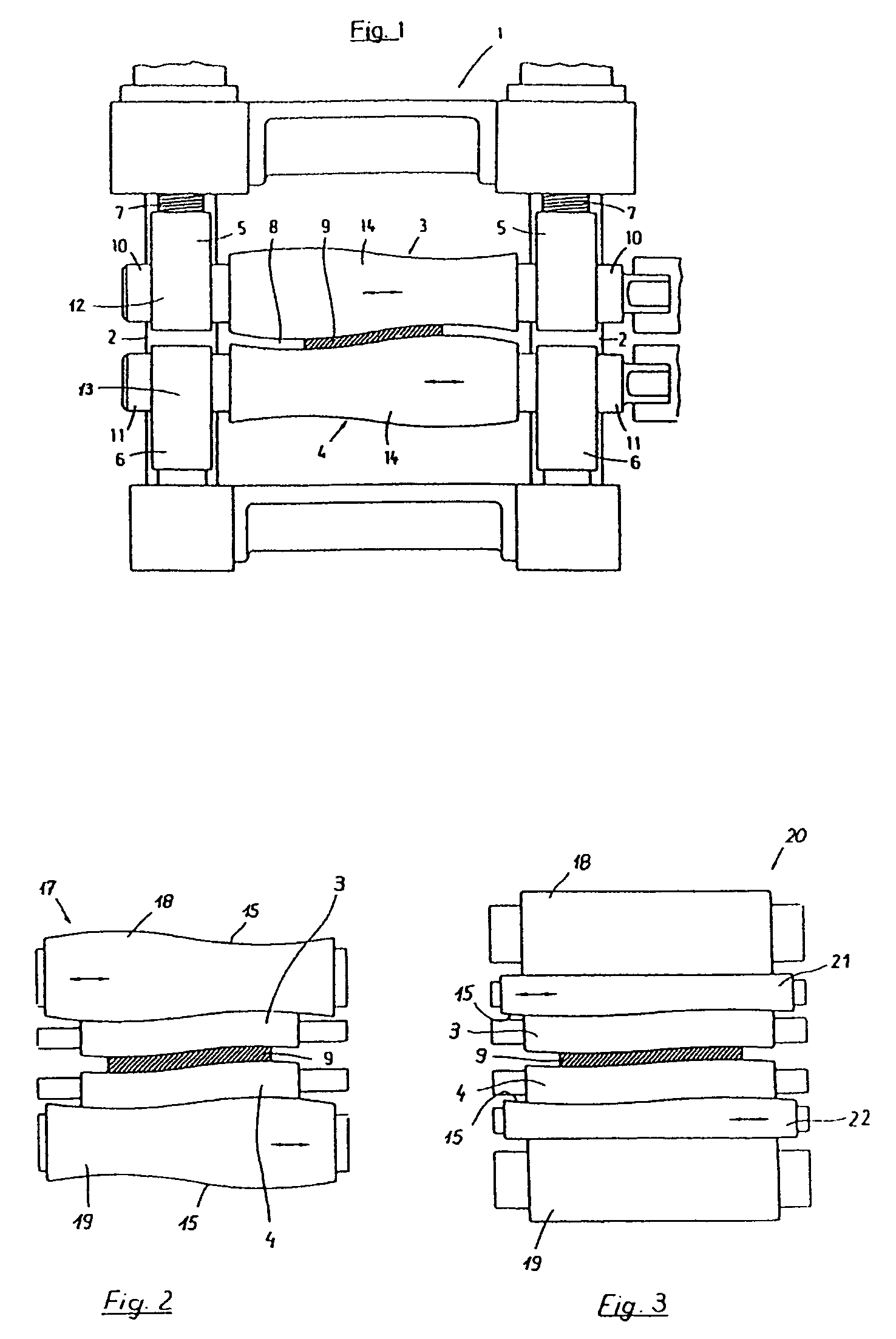
[0047]Various types of rolling stands that are considered for application of the invention and which have known basic structure in the prior art, for example EP-B 0 049 798, to which the invention is here applied are schematically represented in FIGS. 1 to 3.

[0048]FIG. 1 shows a two-high rolling stand 1 with stand uprights 2 and a pair of work rolls 3, 4, which are rotatably supported in chocks 5, 6 in the two stand uprights 2. Adjusting devices 7 make it possible to adjust the two work rolls 3, 4 with respect to the rolled strip 9 running through the roll gap 8. The two work rolls 3, 4 are supported in an axially displaceable manner by means of the roll necks 10, 11 in the chocks 5, 6, which also comprise displacing devices 12, 13. The roll barrels 14 of the two work rolls 3, 4 are provided with a curved barrel contour 15 over their entire effective barrel length, these barrel contours 15 complementing one another in a specific relative axial position of the work rolls in the unloa...


PUM

PropertyMeasurementUnit
Timeaaaaaaaaaa
Angleaaaaaaaaaa
Angleaaaaaaaaaa

Abstract

In the case of a rolling stand for producing rolled strip, which is provided with rolls which are axially displaceable with respect to one another, have a curved contour running over the entire effective barrel length and complement one another exclusively in a specific relative axial position of the rolls in the unloaded state, it is intended for the thickness profile of the roll gap over the active roll barrel length to be varied by axial displacement of the rolls provided with a roll barrel contour in relation to one another in such a way that a strip that is planar and free from undulations is obtained. This takes place by the profile of the barrel contour of the rolls of a pair of rolls being formed by a trigonometric function and the roll gap contour also being formed by a trigonometric function in dependence on the profile of the barrel contour and the position of the rolls within the axial displacement region.

Description

BACKGROUND OF THE INVENTION[0001]The invention relates to a rolling stand for producing rolled strip, with work rolls which are supported if appropriate on backup rolls or backup rolls and intermediate rolls. The work rolls and / or backup rolls and / or intermediate rolls are arranged such that they are axially displaceable with respect to one another in the rolling stand. Each roll of at least one of these pairs of rolls has curved contour running over the entire effective barrel length. These two barrel contours exclusively complement one another at a specific axial position of the rolls of the pair of rolls with respect to each other and in the unloaded state.[0002]To produce a planar rolled strip with a defined cross-sectional profile, it is necessary to set contour-influencing measures, such as for example the use of roll bending devices, with which the application of rolling force to the strip and the distribution of the exiting thickness over the width of the strip can be influe...

Claims


Application Information

Patent Timeline
IPC IPC(8): B21B27/02B21B13/14B21B37/40
CPCB21B13/142B21B37/40
Inventor SEILINGER, ALOISMAYRHOFER, ANDEASKAINZ, ALEXANDER
Owner PRIMETALS TECH AUSTRIA GMBH
Learn More