High-efficiency, large angle, variable displacement hydraulic pump/motor

a variable displacement, hydraulic pump technology, applied in the direction of positive displacement liquid engine, gearing, coupling, etc., can solve the problem of reducing the friction torque the mode of fluid leakage that presents a higher risk, and the leakage of the valve plate, so as to reduce assembly and manufacturing cost, the effect of large angle and greater flow area

Inactive Publication Date: 2006-03-09
ENVIRONMENTAL PROTECTION AGENCY US
View PDF9 Cites 12 Cited by
  • Summary
  • Abstract
  • Description
  • Claims
  • Application Information

AI Technical Summary

Benefits of technology

[0026] The present invention achieves higher efficiencies over a broader-range of displacement and speed than prior art due to the much higher displacement angles achieved by the incorporation of several novel design features. For a given displacement, the large angle of the present invention allows reduced piston diameter, reduced barrel diameter, reduced bearings size, reduced valve plate to barrel contact area, lower piston forces and lower ball to socket forces (all resulting in reduced friction and reduced cost).
[0027] Important to achieving high efficiency across small and large displacements is the discovery of effective strategies for (1a) minimizing flow and compressibility losses and fluid leakage, (1b) minimizing mechanical losses, and (1c) minimizing the chance of tipping. “Tipping” is a mode of fluid leakage that presents a higher risk at large angles, caused by momentary unseating of the cylinder barrel from the valve plate on which it normally rotates.
[0028] The present invention is based in part on a realization that a large displacement angle provides advantages for mechanical and hydraulic efficiency. A large displacement angle provides a longer stroke for each piston, which allows a smaller diameter piston and cylinder and a smaller piston notch circle, leading to lower fluid leakage losses and lower piston loads which in turn lead to less friction in the lower ball socket of each piston rod. A smaller piston notch circle also leads to lower valve plate leakage and lower friction torque on the valve plate. The invention therefore attains the maximum possible displacement angle by overcoming the shortcomings encountered in the prior art.

Problems solved by technology

“Tipping” is a mode of fluid leakage that presents a higher risk at large angles, caused by momentary unseating of the cylinder barrel from the valve plate on which it normally rotates.
A smaller piston notch circle also leads to lower valve plate leakage and lower friction torque on the valve plate.

Method used


Image

  • High-efficiency, large angle, variable displacement hydraulic pump/motor
  • High-efficiency, large angle, variable displacement hydraulic pump/motor
  • High-efficiency, large angle, variable displacement hydraulic pump/motor

Examples


Embodiment Construction

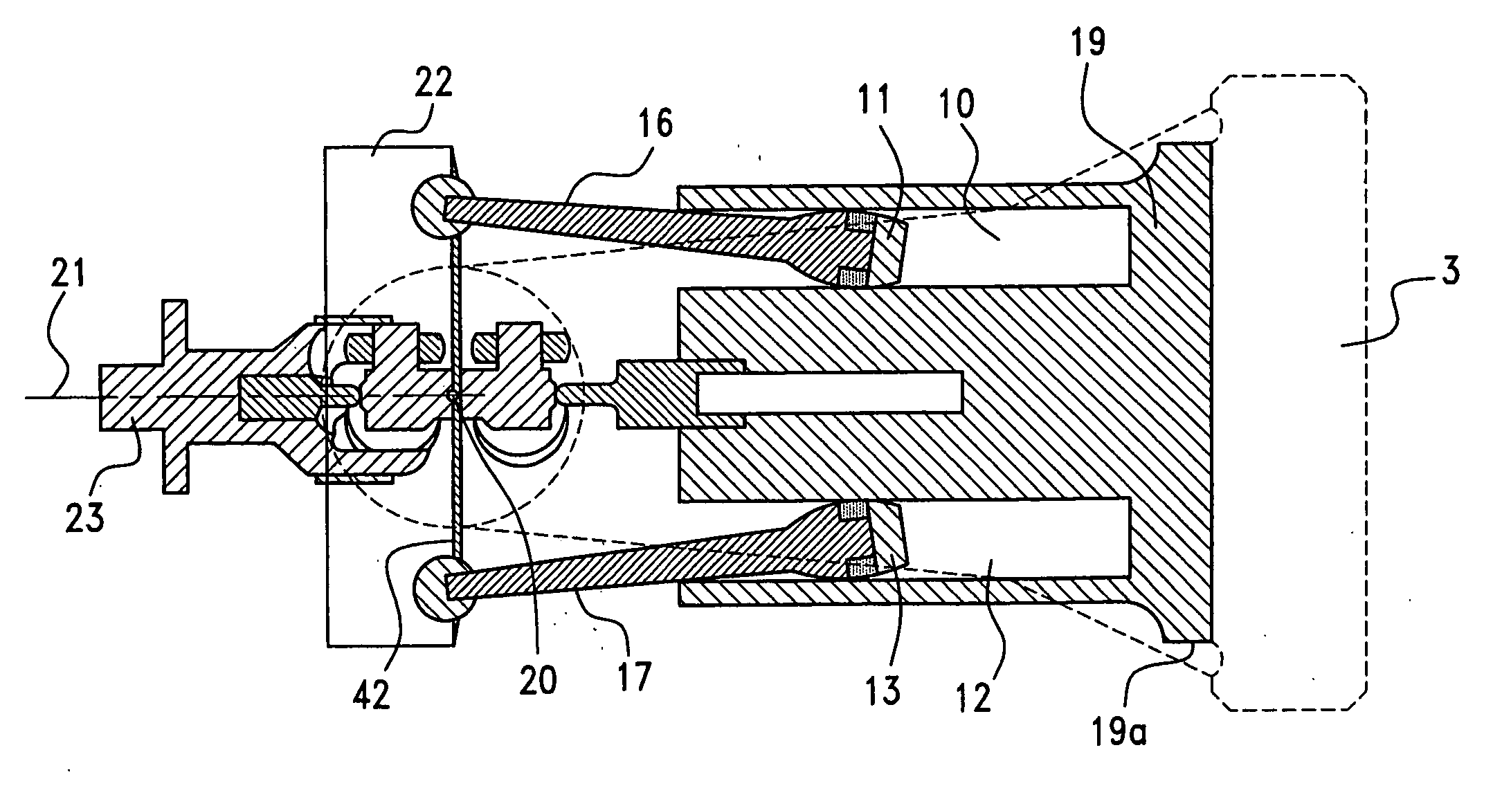
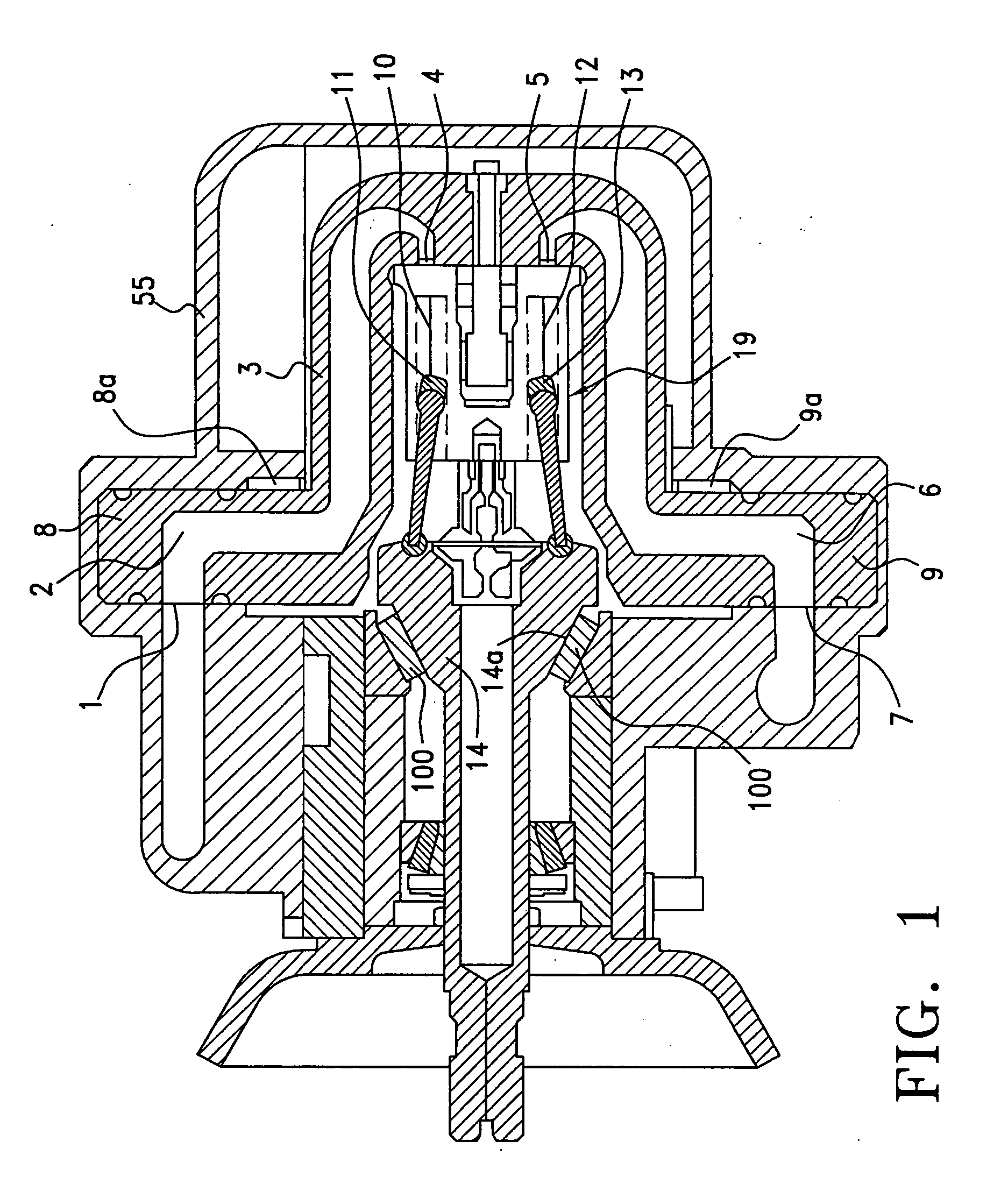
[0078] First, the basic operation of the invention shall be described by following the flow of fluid through a representative embodiment of the invention depicted in FIG. 1 operating as a motor.

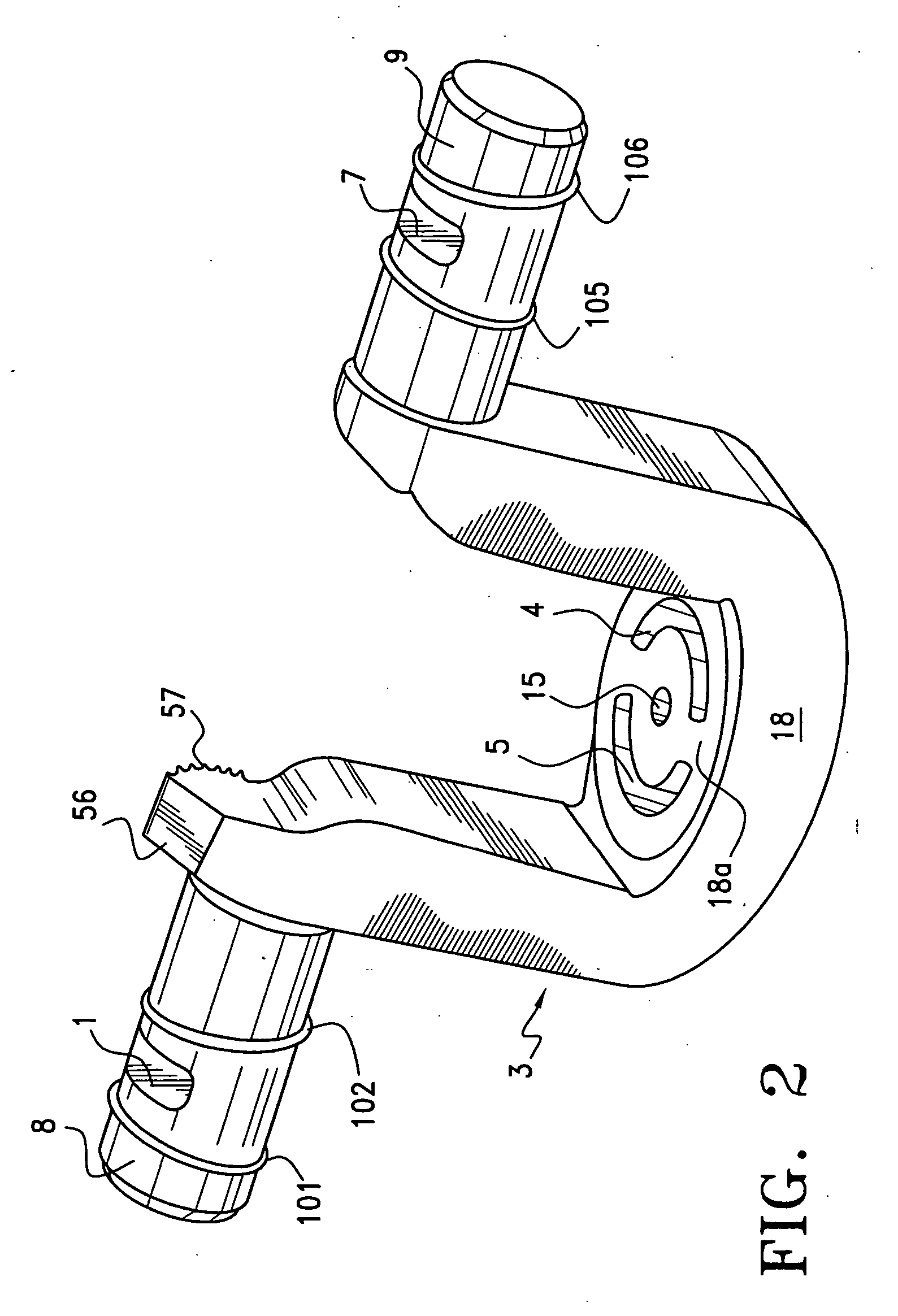
[0079] Referring to FIG. 1, fluid at a high pressure enters at yoke radial port 1 and passes through fluid passage 2 within pivotable yoke 3. Both fluid passages 2 and 6 are preferably of constant cross sectional area. The fluid then enters the valve plate port 4 at which point it begins to participate in a work producing cycle. In this cycle, high pressure fluid entering cylinder 10 pushes reciprocating piston 11 downward which exerts a force on driveshaft (input / output shaft) 14 causing it to rotate. About half of the additional pistons (not shown) will also be participating in various stages of their power stroke at any given time. Simultaneously, piston 13 is taking part in an expelling stroke (shared by the remaining pistons), traveling upward in cylinder 12 acting to expel the now low ...


PUM


Abstract

A variable displacement hydraulic / pump motor has a yoke with a pair of shafts aligned to define a yoke pivot axis and connected to a valve plate therebetween having intake and discharge apertures. A rotatable cylinder barrel has piston cylinders open at one end to receive a piston head and opening through fluid ports at another end, flush against the valve plate surface. A drive block is mounted on an input / output shaft for rotation about a central axis of rotation inclined at an angle relative to the longitudinal axis of the cylinder barrel which may be changed by a drive engaging the yoke at a point near its pivot axis. Loads on bushings supporting the yoke shafts are reduced by providing radially extending fluid ports in the shafts and in communication with the intake and discharge apertures of the valve plate.

Description

FIELD OF THE INVENTION [0001] The general field of application of the invention is in power transmission devices, particularly variable displacement pump / motors for hybrid automotive use. THE PRIOR ART [0002] The growing utilization of automobiles greatly adds to the atmospheric presence of various pollutants including oxides of nitrogen and greenhouse gases such as carbon dioxide. Hybrid powertrains have been proposed in a quest for approaches which could significantly improve the efficiency of fuel utilization for automotive powertrains. [0003] Hydraulic pump / motors are suited to many power transmission applications. An emerging application of these devices is in hybrid powertrains for automobiles. An example of such an application is disclosed in U.S. Pat. No. 5,495,912, “Hybrid Powertrain Vehicle” (Gray et al.). U.S. Pat. No. 5,495,912 discloses a drivetrain in which an internal combustion engine provides prime power to a hybrid vehicle while a subsystem consisting in part of on...

Claims


Application Information

Patent Timeline
Patent Type & Authority Applications(United States)
IPC IPC(8): F04B3/00F04B27/08F04B1/12F04B1/20F04B1/32
CPCF04B1/124F04B1/128F16H2039/005F04B1/328F04B1/2092
Inventor GRAY, CHARLES L. JR.MOSKALIK, ANDREW J.BRUSSTAR, MATTHEW J.GILL, DAVID K.FUQUA, KEVIN BERENTMOFFAT, CRAIG DOUGLAS
Owner ENVIRONMENTAL PROTECTION AGENCY US
Why Eureka
Try Eureka