
Multi-CPU system of easy expansion

A CPU module and signal technology, applied in the field of multi-CPU systems that are easy to expand, can solve the problems of increased production and maintenance costs, large space occupation, and unfavorable system integration, so as to reduce production and maintenance costs, occupy small space, and have strong expansion capabilities. Effect

Active Publication Date: 2007-10-03
SHENZHEN MINDRAY BIO MEDICAL ELECTRONICS CO LTD +1
View PDF0 Cites 5 Cited by
  • Summary
  • Abstract
  • Description
  • Claims
  • Application Information

AI Technical Summary

Problems solved by technology

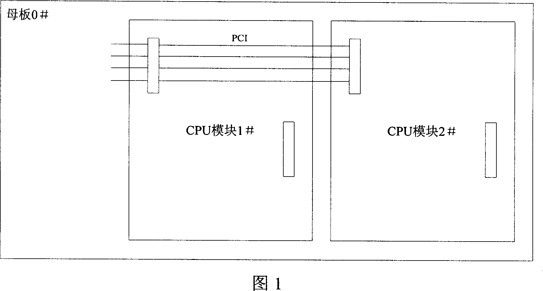
However, most of the existing connections between multiple CPU modules and the motherboard adopt a tiled structure. Corresponding spaces are reserved for multiple CPU modules on the motherboard in advance, and then the CPU modules are fastened to the respective motherboards as required. The corresponding position of the module occupies a large space, which is not conducive to system integration, resulting in a very limited number of scalable CPU modules
Another outstanding disadvantage of the tiled structure is that each CPU module must be different in order to adapt to the processing of asymmetrical signals, which increases the cost of production and maintenance.
In addition, the expansion capability of the flat structure is also heavily dependent on the foresight of future new functions at the time of initial design, but such a foresight is difficult to achieve accurately
If the estimated processing capacity required in the future is overestimated, the design difficulty will increase and the system cost will increase significantly; System, in addition, multiple CPU modules with a flat structure and subboard scheme are different for each CPU module, and the production and maintenance costs are still relatively high

Method used


Image

  • Multi-CPU system of easy expansion
  • Multi-CPU system of easy expansion
  • Multi-CPU system of easy expansion

Examples


specific Embodiment approach 1

[0041] Specific implementation mode one: an easily expandable multi-CPU system consisting of four CPU modules

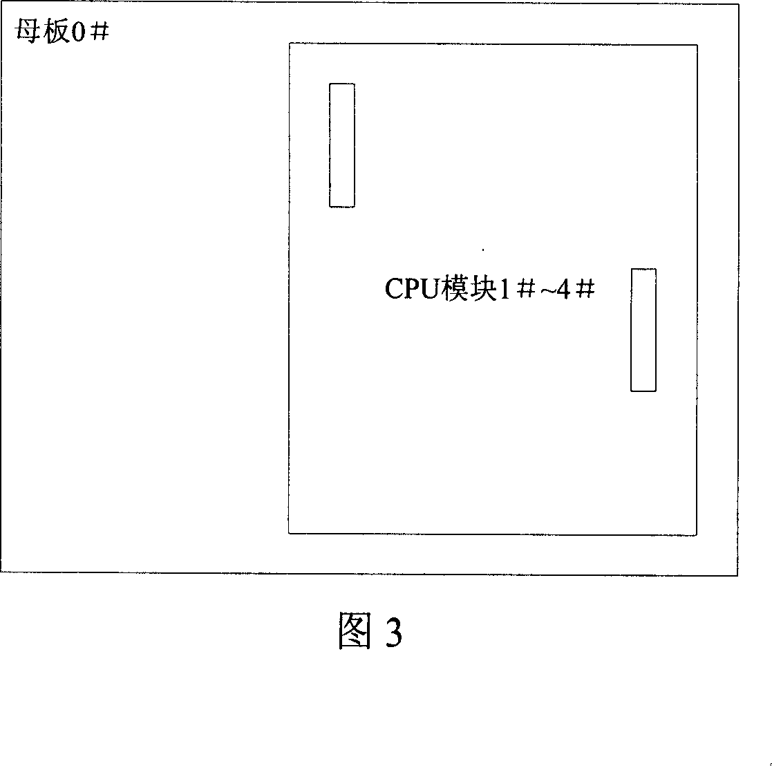
[0042] This easy-to-expand four-CPU system includes motherboard 0# and four CPU modules 1#-4#. CPU modules 1#~4# are modules with sub-board interfaces and master functions of the main equipment, including modules designed by using the general-purpose processor CPU and modules designed by using the digital signal processor DSP. They are connected layer by layer up and down. In this way, a stacked structure is formed. The CPU module 1# on the lowest layer is connected to the motherboard 0#, and the signals of the stacked daughter board interface are routed under the bus specification.

[0043] CPU modules 1#~4# are identical CPU modules, and there is a group of IDs used to identify each CPU module outside the bus, so as to automatically identify their respective positions in the system.

[0044] The communication between CPU modules 1#~4# is coordinated by setting up ...

specific Embodiment approach 2

[0057] Specific implementation mode two: Another easily expandable multi-CPU system consists of three CPU modules and one non-CPU function module

[0058] Embodiment 2 is basically the same in composition and routing as Embodiment 1, except that module 3# is a non-CPU PCI function module. Fig. 13 is a schematic diagram of its PCI reset route. The non-CPU functional module 3# receives the reset signal PCIRESET output by the adjacent CPU module 2# or 4# through the temporary signal TRST. In addition, the interrupt can be realized by directly connecting the interrupt signal output by it to the PCI interrupt signal INT#.


PUM


Abstract

The present invention discloses an extendible multiple CPU system, including mother plate and several CPU modules. The described every CPU module is equipped with a fastening board interface. It is characterized by that said several CPU modules are formed into a laminated type structure by adopting layer-by-layer fastening connection mode from top to bottom, the lowest CPU module is fastening-connected on the mother plate. The communication between the described several CPU modules can be coordinated by means of setting route.

Description

technical field [0001] The present invention relates to the combination of two or more CPU modules, and also relates to the interconnection or simultaneous processing of transmission requests for several programs among multiple CPU modules, especially relates to an easily expandable multi-CPU system. Background technique [0002] For many electronic devices, the processing power of the CPU often becomes the bottleneck of the system upgrade. Adding new functions often leads to a heavier load on the CPU, and if the margin of the original design is not enough, the hardware circuit will have to be redesigned, a CPU with a stronger processing capability or a multi-CPU system will have to be used. This meant huge design work and high production costs, resulting in product upgrades that cost even more than developing a new product. [0003] In order to avoid this kind of problem, the usual way is to reserve enough margin for the processing power of the CPU in the initial design to...

Claims


Application Information

Patent Timeline
Patent Type & Authority Applications(China)
IPC IPC(8): G06F13/40
CPCG06F15/17
Inventor 姚力陈巍
Owner SHENZHEN MINDRAY BIO MEDICAL ELECTRONICS CO LTD
Learn More