Image correction device and coating unit thereof

A coating and patterning technology, which is applied to the formation of conductive patterns, devices for applying liquid to surfaces, coatings, etc., can solve problems such as longer correction time for defective parts, and achieve the effect of simple structure

Inactive Publication Date: 2007-10-03
NTN CORP
View PDF2 Cites 16 Cited by
  • Summary
  • Abstract
  • Description
  • Claims
  • Application Information

AI Technical Summary

Problems solved by technology

[0005] However, in the conventional pattern correction device, when the defect portion is large, the correction liquid must be applied to the defect portion several times, and the coating needle must be returned

Method used


Image

  • Image correction device and coating unit thereof
  • Image correction device and coating unit thereof
  • Image correction device and coating unit thereof

Examples


Embodiment Construction

[0039] (Embodiment 1)

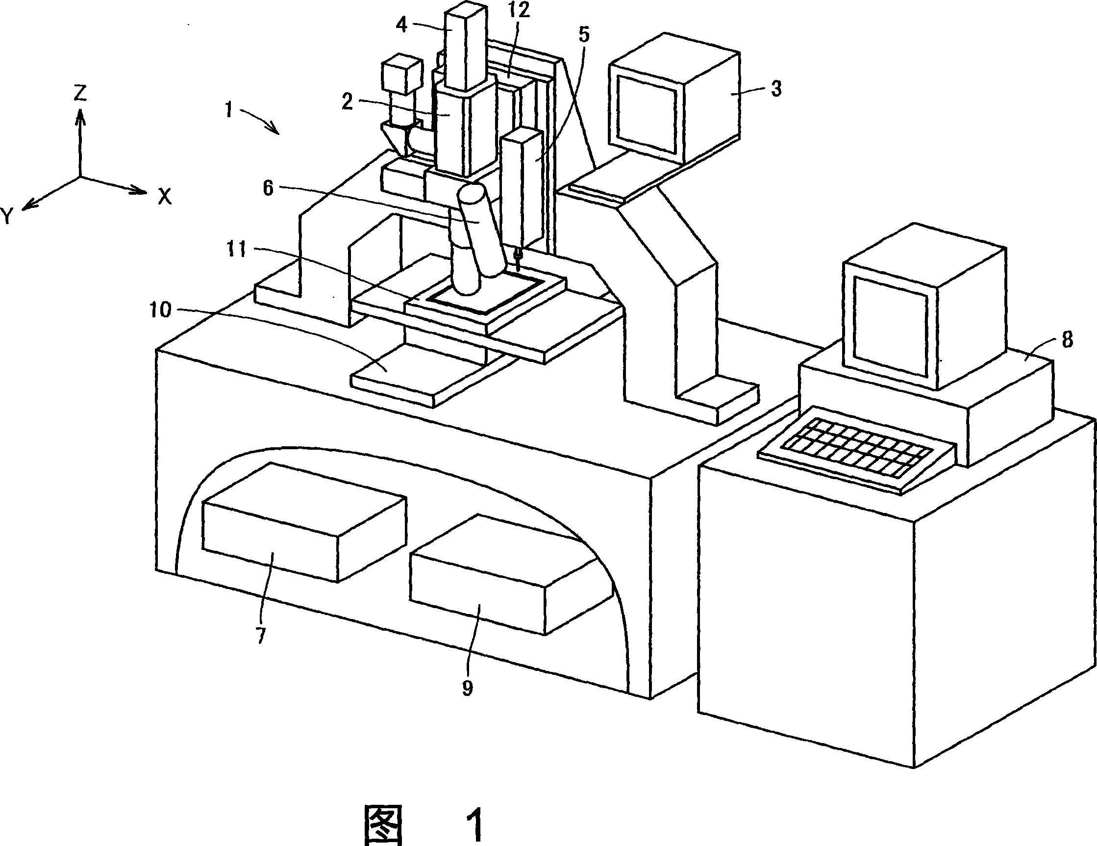
[0040] Fig. 1 is a view showing the overall structure of a pattern correction device according to Embodiment 1 of the present invention. In Fig. 1, figure correcting device 1 has: the observation optical system 2 that observes substrate surface; The monitor 3 that displays the observed image; Laser unit 4; Coating mechanism unit 5 that attaches the correction fluid to the tip of the coating needle and coats it on the defective part of the substrate; Substrate heating unit 6 that heats the correction fluid coated on the defective part; Identification The image processing part 7 of the defect part; the host computer 8 of the overall control device; and the control computer 9 of the control device mechanical part operation. In addition, there are: an XY-axis stage 10 for moving a substrate having a defective portion in the XY direction (horizontal direction); a claw portion 11 for holding the substrate on the XY-axis stage 10; The Z-axis stage 12 etc. wh...


PUM


Abstract

A pattern modification device (1) is discloses, in which a coating unit (20) is provided with: a container (21) having a first hole (21a) at a bottom portion for injecting a modification liquid (22);a coating needle (24) haiving a diameter approximately same with that of the first hole (21a); a cylinder which moves the container (21) and the coating needle (24) up and down, and relatively moves the container (21) and the coating needle (24) to each other so that a front end portion (24a) of the coating needle is projected from the first hole (21a) and the modification liquid (22) is attachedto the front end portion (24a). Accordingly, compared with a conventional technic in which the coating needle needs to be reciprocated between the container and a fault portion, the pattern modification device of the invention can rapidly modify the fault portion by a simple structure.

Description

technical field [0001] The present invention relates to a pattern correcting device and its coating unit, and more particularly to a pattern correcting device and its coating unit for correcting defective parts of minute patterns formed on a substrate. More specifically, the present invention relates to pattern correction for correcting opening defects of electrodes, defects of ribs (partition walls) of plasma displays, white defects of liquid crystal color filters, defects of masks, etc., which occur in the manufacturing process of flat panel displays Apparatus and coating unit for it. Background technique [0002] In recent years, with the increase in size and high definition of flat-panel displays such as plasma displays, liquid crystal displays, and EL displays, in the manufacturing process of displays, defects may occur on electrodes and ribs on the substrate, or on liquid crystal color filters. The probability of defects in the coloring layer becomes greater. Therefo...

Claims


Application Information

Patent Timeline
IPC IPC(8): H01J9/50G02F1/133G02F1/1335G03F1/00B05C1/02H01J11/22H01J11/34H01J11/36H05K3/10H05K3/22
CPCY02W30/82
Inventor 松岛昌良山中昭浩小池孝誌
Owner NTN CORP
Why Eureka
Try Eureka