Power free radio monitor system and subbase station for the system
A monitoring system, technology without power supply, applied in the direction of diversity/multi-antenna system, transmission system, radio/inductive link selection arrangement, etc., can solve the problems of indeterminable device location, large size, etc.
- Summary
- Abstract
- Description
- Claims
- Application Information
AI Technical Summary
Problems solved by technology
Method used
Image
Examples
no. 1 approach
[0058] (Structure of wireless monitoring system without power supply)
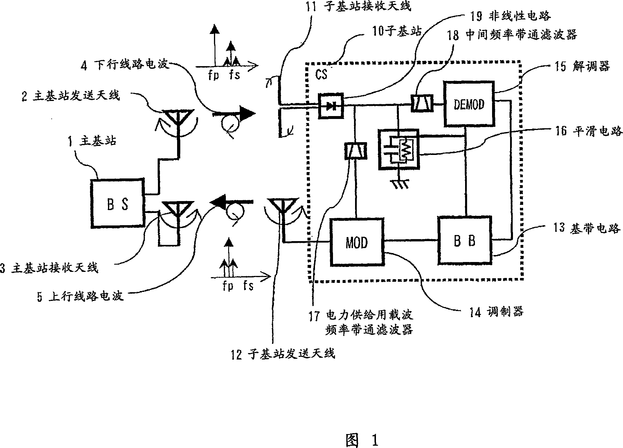
[0059] FIG. 1 is a schematic diagram showing the configuration of a power-free wireless monitoring system according to a first embodiment of the present invention. In the wireless monitoring system without power supply according to the present embodiment, power transmission and communication are performed between main base station (BS) 1 and sub base station (CS) 10 .
[0060] (Structure of main base station)
[0061] The master base station 1 includes a master base station transmitting antenna 2 as a circularly polarized antenna, and a master base station receiving antenna 3 as a circularly polarizing antenna having a polarization characteristic reversed to that of the master base station transmitting antenna 2 .
[0062] (Operation of main base station)
[0063] In the downlink radio wave 4 from the main base station 1 to the sub-base station 10, the non-modulated carrier wave (circular polarized wave)...
no. 2 approach
[0088] (Structure of sub base station)
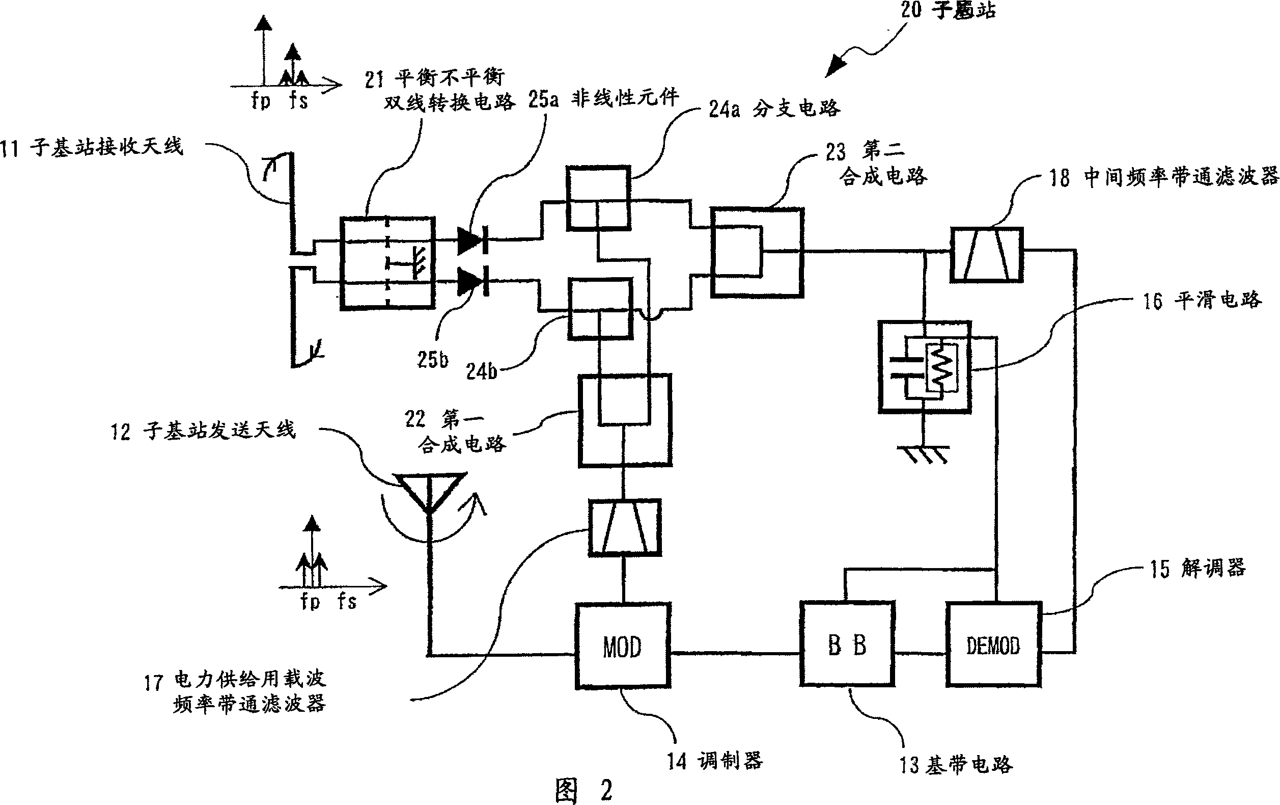
[0089] FIG. 2 is a schematic diagram showing the configuration of a sub base station of a wireless monitoring system without power supply according to a second embodiment of the present invention. Except for the configuration and operation of the sub-base station described below, it is the same as the passive wireless monitoring system of the first embodiment.
[0090] The sub-base station 20 of this embodiment includes: a sub-base station reception antenna 11 as a balanced circularly polarized wave antenna, and a sub-base station transmission antenna as a circularly polarized wave antenna having a polarization characteristic reversed to that of the sub-base station reception antenna 11. Antenna 12, baseband circuit (BB) 13, modulator (MOD) 14, demodulator (DEMOD) 15, smoothing circuit 16, carrier frequency bandpass filter 17 for power supply, intermediate frequency bandpass filter 18, balanced Balanced two-line conversion circuit 21, ...
no. 3 approach
[0097] (Structure of sub base station)
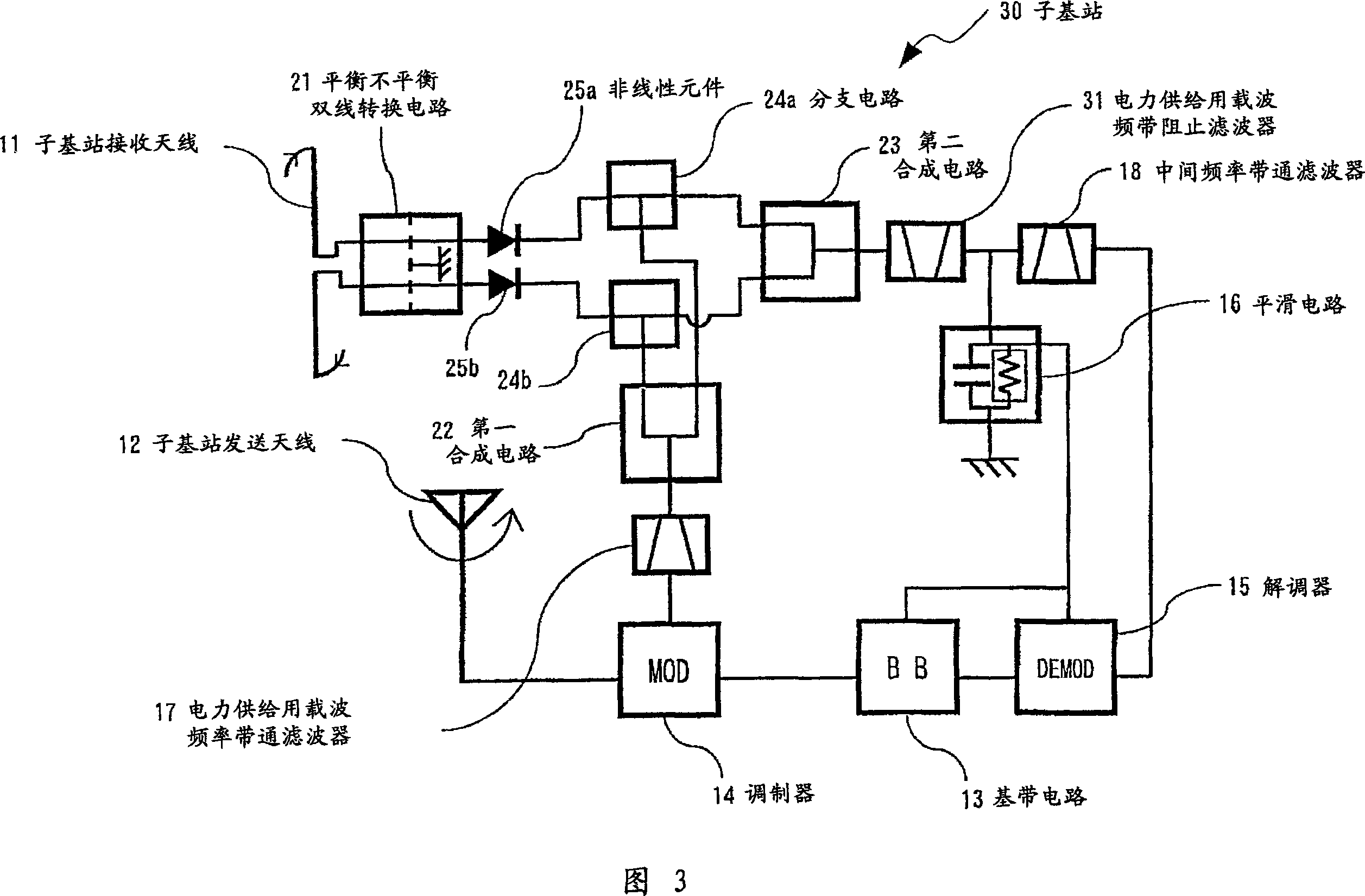
[0098] Fig. 3 is a schematic diagram showing the configuration of a sub-base station of a passive wireless monitoring system according to a third embodiment of the present invention. Descriptions of the same parts as those in the various embodiments of the present invention described above are omitted.
[0099] The sub base station 30 of this embodiment differs from the second embodiment in that a carrier frequency band rejection filter 31 for power supply is inserted between the intermediate frequency band pass filter 18 and the second synthesis circuit 23 .
[0100] In order to prevent the high-frequency signal (the carrier wave for power supply and the carrier wave for signal transmission) from passing through the demodulator 15, a carrier frequency band-stop filter 31 for power supply is provided before the intermediate frequency band-pass filter 18 provided. This is to send only the component of the carrier wave for signal transmi...
PUM
 Abstract
Description
Claims
Application Information
 - R&D
- Intellectual Property
- Life Sciences
- Materials
- Tech Scout
- Unparalleled Data Quality
- Higher Quality Content
- 60% Fewer Hallucinations
Browse by: Latest US Patents, China's latest patents, Technical Efficacy Thesaurus, Application Domain, Technology Topic, Popular Technical Reports.
© 2025 PatSnap. All rights reserved.Legal|Privacy policy|Modern Slavery Act Transparency Statement|Sitemap|About US| Contact US: help@patsnap.com


