Engine power assembly

A technology of engine and frame, which is applied in the direction of engine components, engine cooling, machine/engine, etc., and can solve problems such as cylinder liner wear and tear

Active Publication Date: 2007-10-03
GENERAL ELECTRIC CO
View PDF0 Cites 12 Cited by
  • Summary
  • Abstract
  • Description
  • Claims
  • Application Information

AI Technical Summary

Problems solved by technology

The cylinder liner may experience further wear where it abuts the engine frame due to repeated combustion loads placed on the cylinder liner

Method used


Image

  • Engine power assembly
  • Engine power assembly
  • Engine power assembly

Examples


Embodiment Construction

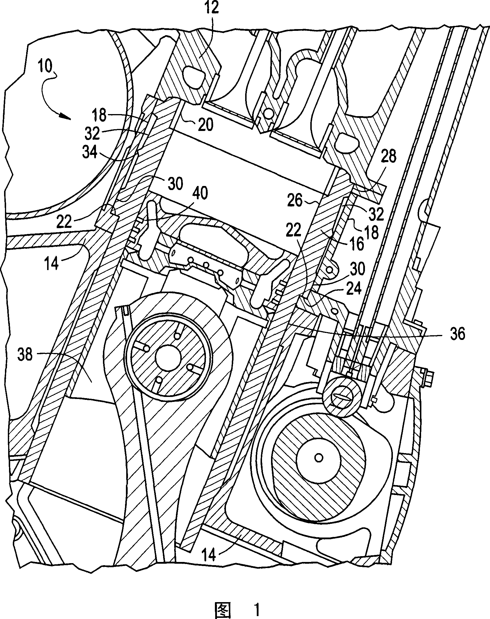
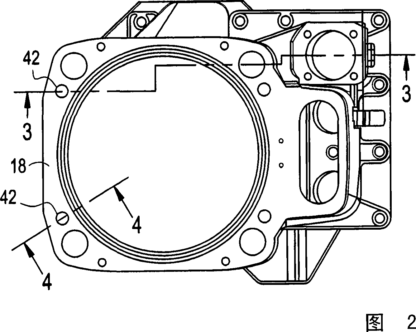
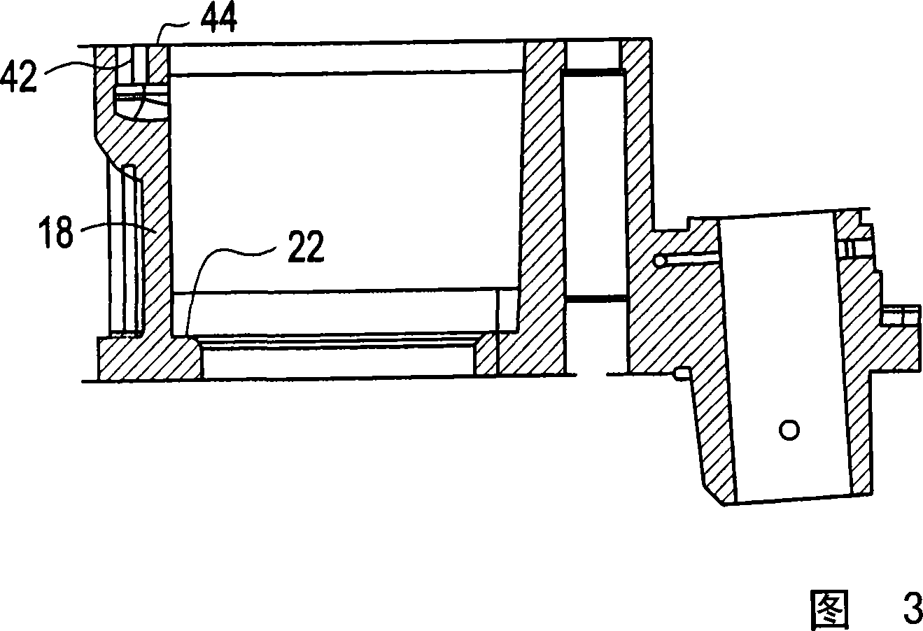
[0015] As shown in FIG. 1 , a first embodiment of an apparatus 10 of the present invention includes a cylinder head 12 , an engine frame 14 , a cylinder liner 16 , a spacer plate or water jacket 18 and a combustion ring 20 . An upward facing flange 22 may be provided on the inner surface of the water jacket 18 , as best shown in FIG. 3 , and a downward facing shoulder 24 may be provided on the outer surface of the cylinder liner 16 . The shoulder 24 is designed to abut against the flange 22 so that the cylinder liner 16 is supported by the water jacket 18 . The water jacket 18 is then supported by the engine frame 14 . This avoids direct support of the cylinder liner 16 by the engine frame 14 , thereby minimizing wear on the cylinder liner 16 .

[0016] A combustion ring 20 is disposed at the junction between the cylinder liner 16 and the cylinder head 12 to protect the head gasket from damage from exposure to the hot combustion gases. For clarity purposes, piston 38 is show...


PUM


Abstract

A locomotive diesel engine, having a cylinder liner and a separate water jacket surrounding the cylinder liner, with a portion of the water jacket being positioned between the cylinder liner and the engine frame, where the cylinder line is supported by the water jacket. An external shoulder on the cylinder liner can be supported by an internal flange in the water jacket, thereby eliminating direct contact between the cylinder liner and the engine frame. A coolant passage can be provided between the water jacket and the cylinder liner, at a point adjacent the topmost between the cylinder liner and the water jacket, above the coolant passage, and a lower liner seal can be provided between the cylinder liner and the engine frame, below the coolant passage. Coolant ports can be provided for coolant flow directly between the cylinder head and the water jacket, with seals in the coolant ports to seal the coolant, independently of the head gasket.

Description

technical field [0001] This invention relates to the field of locomotive diesel engines and in particular to engine components associated with coolant flow and heat removal from structures surrounding combustion chambers. Background technique [0002] In any internal combustion engine utilizing a separate cylinder liner, there are some problems in the way the engine frame, cylinder head, cylinder liner and water jacket are assembled. One of these problems is coolant leakage. The mating surfaces between the cylinder block or cylinder liner and the associated cylinder head are often subject to combustion products and coolant leakage, particularly in high compression diesel engines used in locomotive applications. These surfaces are often fitted with head gaskets in between, and the head gaskets are often exposed to the high temperatures and pressures of combustion products generated in the combustion chamber, which accelerates the wear of the gaskets and the attendant leakage...

Claims


Application Information

Patent Timeline
Patent Type & Authority Applications(China)
IPC IPC(8): F02F1/16F01P3/02
CPCF02F1/16F01P3/02F01P11/04F01P2003/021F01P2003/024F02F2001/106F02F1/163
Inventor P·L·弗林J·S·勒贝格J·P·道威尔B·雷科德
Owner GENERAL ELECTRIC CO
Why Eureka
Try Eureka