Corn harvestry dividual unit of combined tomy table for reaping corn
A corn, split technology, applied in the direction of harvesters, agricultural machinery and implements, applications, etc., can solve the problems of long cycle, high manufacturing cost, damaged machinery, etc.
- Summary
- Abstract
- Description
- Claims
- Application Information
AI Technical Summary
Problems solved by technology
Method used
Image
Examples
Embodiment 1
[0032] Embodiment 1. The corn harvesting split unit of the corn harvesting combined header
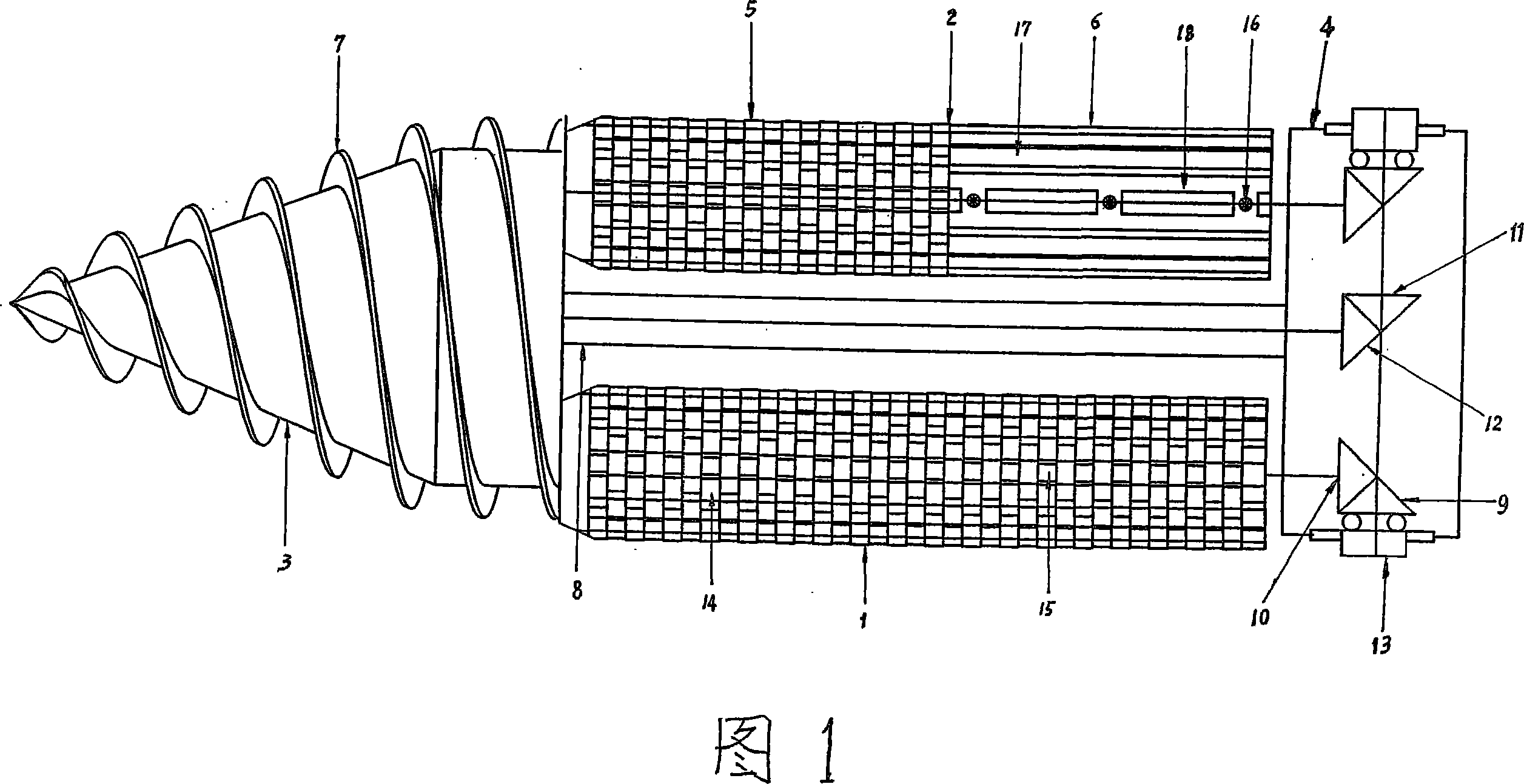
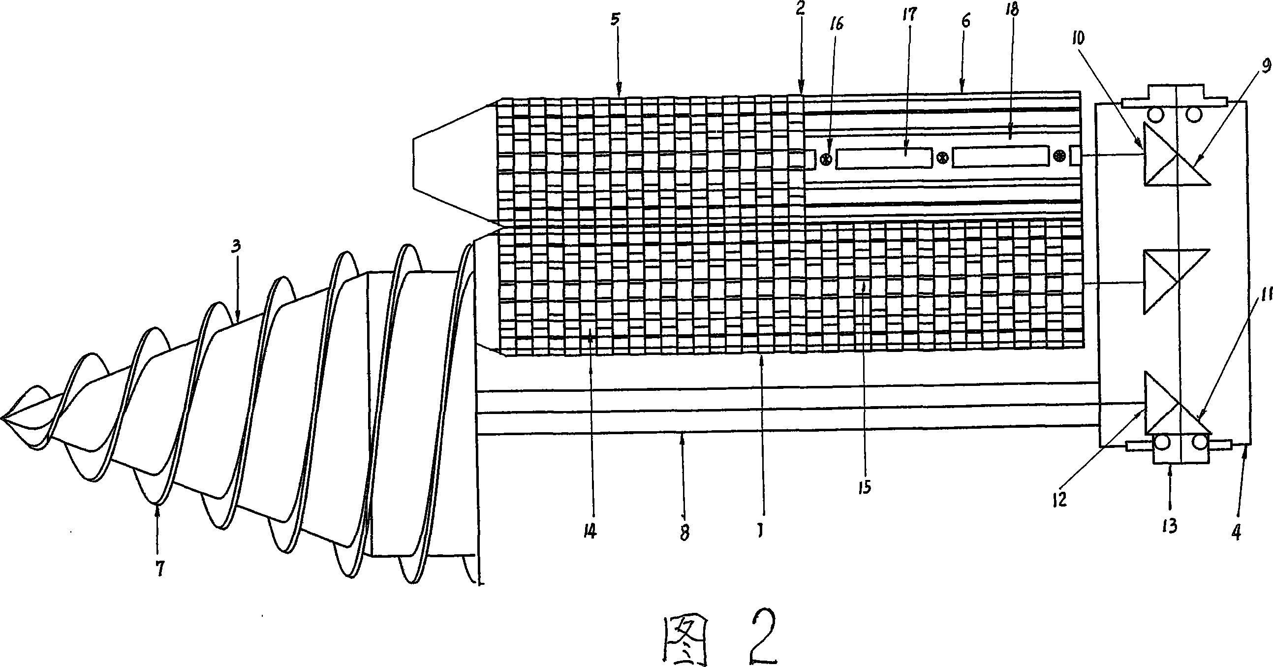
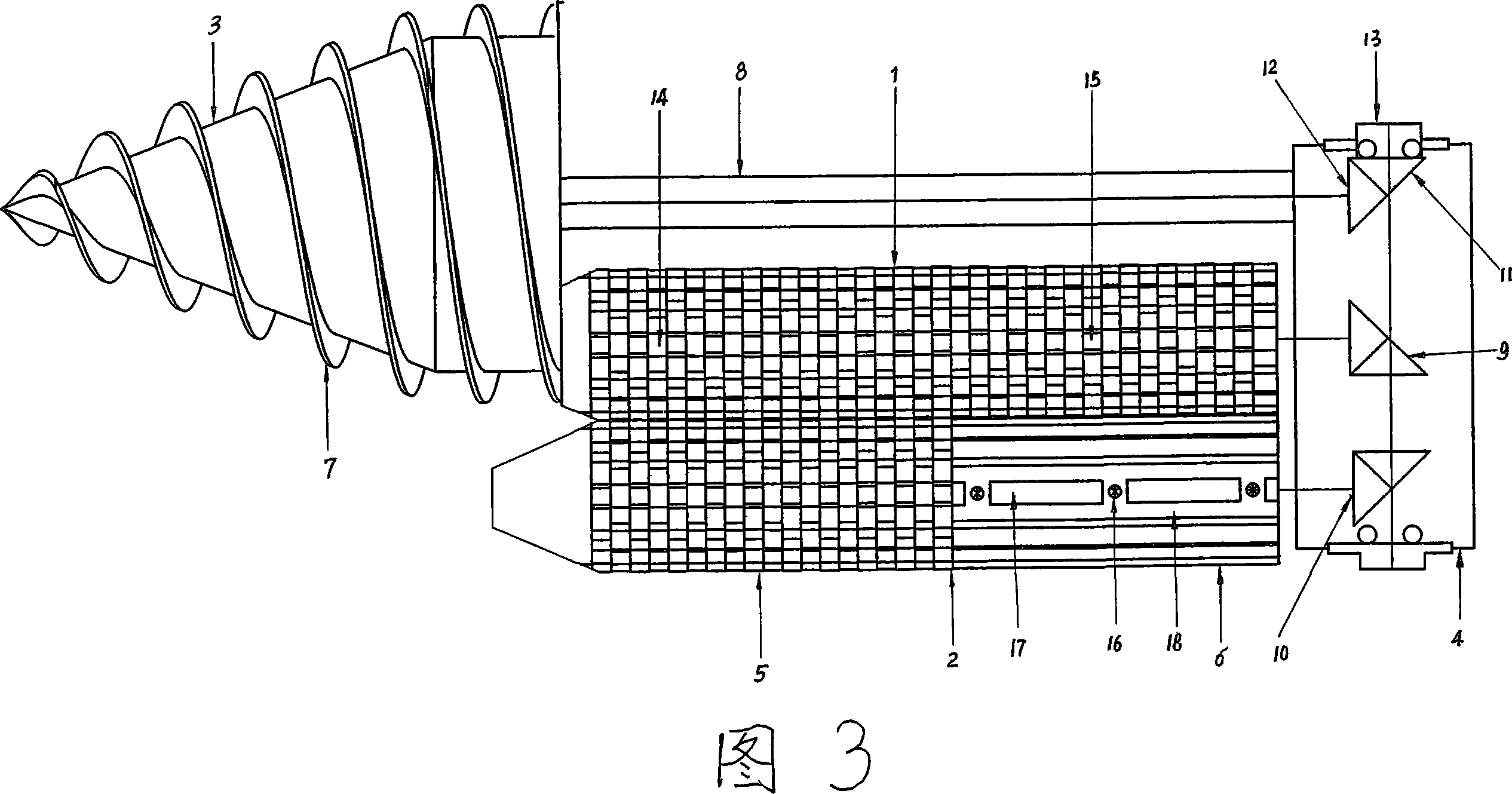
[0033] The specific structure of the corn harvesting split unit of the corn harvesting combined header of this embodiment is jointly shown by Figures 1 to 11, and Figures 1 to 4 jointly show the overall structure of this corn harvesting split unit, including a drive With transmission mechanism, drive mechanical box 4 and drive / transmission shaft 13, bar 8, gear 9~12 etc., the driving mechanical box 4 shown in each figure is a pair of corn ear picking rollers 1,2 and stirring The driving mechanical box of the dragon-style corn splitter and the reel 3, the driving mechanical box 4 is provided with: a drive / transmission main shaft and a pair of gears 9 and 10 of the corn picking rollers 1 and 2, and the drive The gears 11 and 12 of the auger type corn splitter and the reel 3 have structures such as gears 11 and 12, and the left and right sides of the drive mechanical box are provided with...
Embodiment 2
[0034] Embodiment 2. The corn harvesting split unit of the corn harvesting combined header
[0035]The general structure of the corn harvesting split unit of the corn harvesting combined header of this embodiment can be shown in conjunction with Fig. 1, Fig. 4, Fig. 5, Fig. 7 and so on. The combined corn harvesting head of this example has different points with embodiment one: 1. the concrete structure of the corn harvesting split unit of this example is shown by Fig. The front top of the center of the two ear picking rollers. 2. In this example, the gear-chain drive / transmission structure is adopted between the driving mechanical box of each split unit, the corn ear picking roller, and the auger-type corn splitting reel. 3. At each corn harvesting port, a pair of corn harvesting ear picking rollers 1 and peeling rollers 2 are arranged above the central rear part of the two rollers and are erected and arranged in a line with two corn peeling wheels that rotate forward and bac...
Embodiment 3
[0036] Embodiment 3. The corn harvesting split unit of the corn harvesting combined header
[0037] The general structure of the corn harvesting split unit of the corn harvesting combined header of this embodiment can be shown in conjunction with Fig. 2, Fig. 4, Fig. 5, Fig. 7 and so on. The combined corn harvesting header of this example has different points from embodiment one and embodiment two: 1. the concrete structure of the corn harvesting split unit of this example is shown in Fig. The grain device is placed on the left front and upper side of the two picking rollers. 2. The transmission wheel 21-belt type drive / transmission structure is used between the driving mechanical box of each split unit of this example and the corn ear picking roller and the auger type corn grain dividing reel. 3. The specific structure of corn harvesting ear-picking roller 1 in pairs at each corn harvesting opening is: its roller core 19 of the ear-picking roller 1 of this example is made of...
PUM
 Abstract
Description
Claims
Application Information
 - R&D
- Intellectual Property
- Life Sciences
- Materials
- Tech Scout
- Unparalleled Data Quality
- Higher Quality Content
- 60% Fewer Hallucinations
Browse by: Latest US Patents, China's latest patents, Technical Efficacy Thesaurus, Application Domain, Technology Topic, Popular Technical Reports.
© 2025 PatSnap. All rights reserved.Legal|Privacy policy|Modern Slavery Act Transparency Statement|Sitemap|About US| Contact US: help@patsnap.com


