Joint device for flexible pipe

A joint device, flexible technology, applied in the direction of hose connection device, pipe/pipe joint/pipe fitting, mechanical equipment, etc., can solve the problems of failure, time waste, difficult penetration, etc., to reduce the construction space, reduce Material usage, effect of reducing manufacturing cost

Inactive Publication Date: 2007-10-10
曾德兴
View PDF1 Cites 3 Cited by
  • Summary
  • Abstract
  • Description
  • Claims
  • Application Information

AI Technical Summary

Problems solved by technology

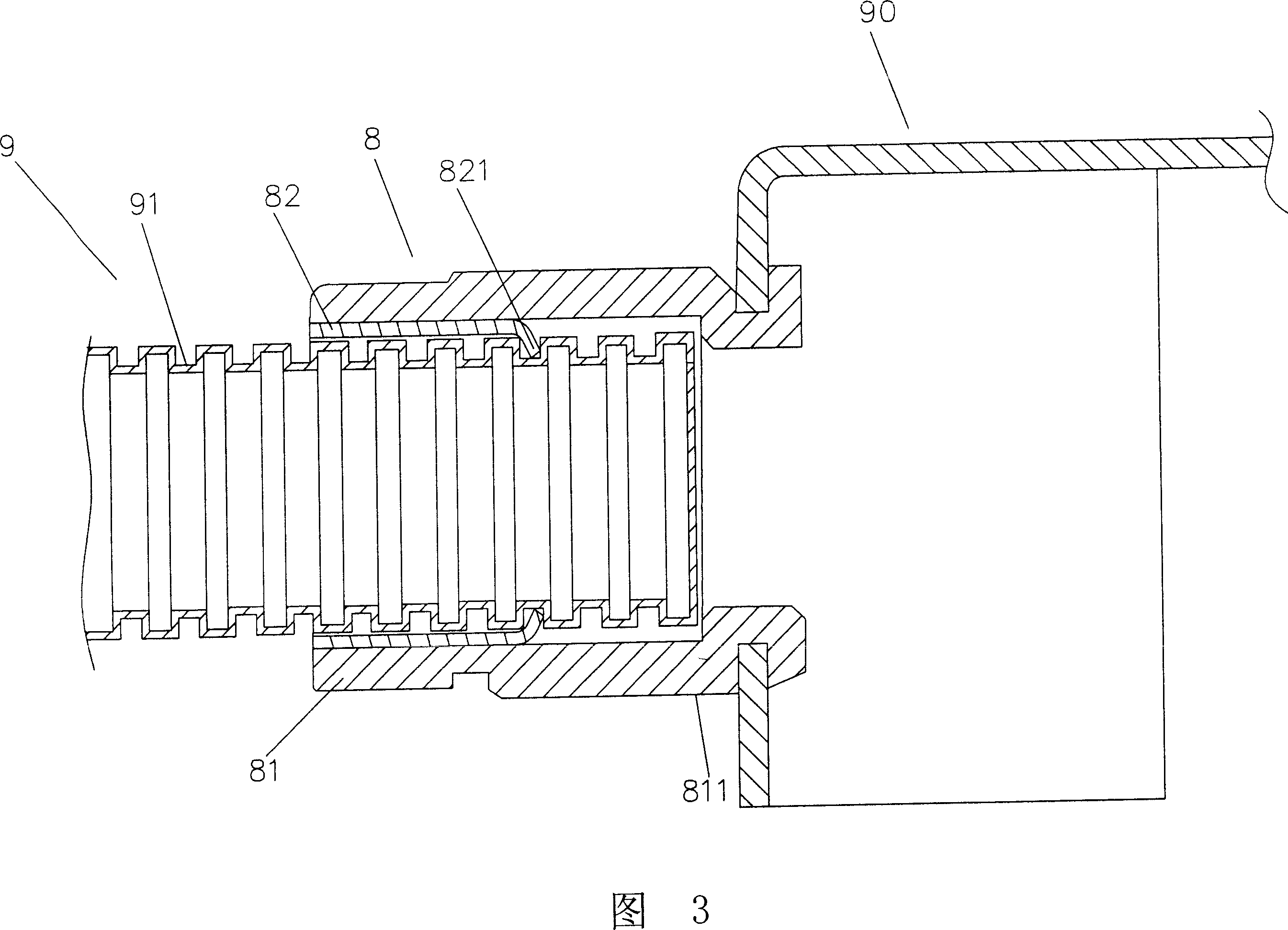
[0006] 1. When inserting the wave tube for combination and fixation, no matter whether it is the hook or the buckle, it only has the positioning effect to prevent the wave tube from being pulled out, and the insertion position and depth cannot be controlled at all, so that the matching Tubes with various functional forms will be inserted too deep as shown in Figure 3, so that the buckle part 811 cannot be pressed, resulting in the inability to achieve the function of snapping or removing with the distribution box 90, and affecting its practical function , it will increase the possibility of failure in the subsequent construction
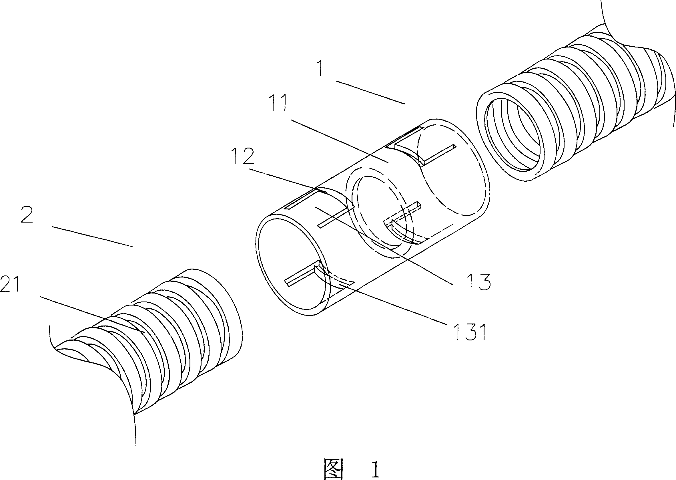
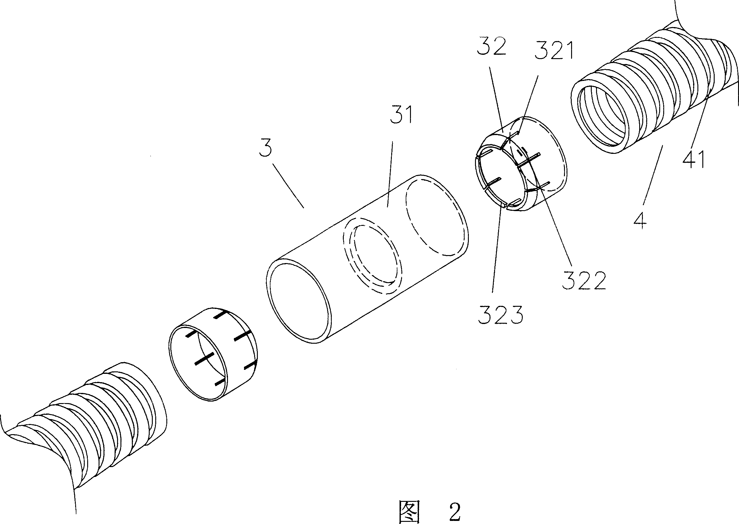
[0007] 2. When the tube body is set with the hook abutting position, it is difficult to effectively prevent seepage due to the large gap of the ㄇ-shaped groove, and when the elastic flap is set, the elastic flap expands outward when the wave tube is inserted, so The gap between the flaps will increase further, so its impermeability is not good. At the same time, when the wave tube is inserted after assembly, as shown in Figure 1, in order to provide the expansion and contraction space of the buckle 13, the outer diameter of the wave tube It will be smaller than the socket and the inner diameter to facilitate passage, so that a tight combination between the two is impossible, and it also causes poor penetration resistance
[0008] 3. In order to have appropriate elasticity, the elastic flaps or hooks must have appropriate lengths, so that the length of the pipe body must be increased accordingly. This will not only cause waste of materials, but also when the piping has space restrictions, it will also cause problems. will affect the usability
[0009] 4. Since the wave tube cannot be withdrawn after it is inserted, when it is necessary to dismantle or modify it during the construction process, it is known that the product has no possibility of replacement, but the joint between the joint and the wave tube must be destroyed forcibly , not only lead to unnecessary waste of cost, but also waste of time

Method used


Image

  • Joint device for flexible pipe
  • Joint device for flexible pipe
  • Joint device for flexible pipe

Examples


Embodiment Construction

[0046] In order to understand more easily the device of the present invention and the effect that can be achieved, the accompanying drawings are described as follows.

[0047] Please refer to Figures 4-5 first, the present invention is mainly composed of at least one gasket ring 5 and a main body 6, wherein the gasket ring 5 is a cut ring body, and the two end faces of the cut part are corresponding slopes , so that the contact surface of the two end surfaces can be larger after they are closed, and can be more tightly bonded, at least one convex rib 51 is provided on the inner peripheral surface, and at least one insert 52 is provided on the outer peripheral surface, and at the same time At least one protruding puller 53 is provided on the outer edge of the washer ring 5. In this embodiment, the puller 53 is two corresponding pullers, which are used as force application points when the washer ring 5 is rotated. , the main pipe body 6 is a hollow circular pipe body, and a guid...


PUM


Abstract

A connector unit of flexible tube is prepared for using hollow round tube body as master tube body and setting guide slot and embedding hole on tube wall at one end of master tube body, using an open ring as backing connection ring, setting convex rib at internal peripheral surface and embedding block at external peripheral surface of blocking connection ring for enabling to socket backing connection ring on external peripheral surface of flexible tube so as to realize purpose of combining flexible tubes together without using any tool.

Description

Technical field: [0001] The invention relates to a joint device of a flexible pipe body, especially a device which is composed of a main body and at least one gasket ring, and can be quickly combined and fixed for the flexible pipe body. Background technique: [0002] In many applications, it is often necessary to use the combination of the pipe body. Among them, the wave pipe with the same circular groove can be bent freely. For the constructor, it really improves the convenience of its construction and is widely used. , please refer to Fig. 1 at first, the joint 1 of the known supply wave pipe combination is provided with a corresponding ㄇ-shaped groove 12 on the pipe body 11, so that an elastic buckle 13 is formed, and the end of the buckle 13 Form a hook 131 concave inward, then after the wave tube 2 is inserted into the nozzle of the joint 1, the hook 131 of the buckle 13 can be hooked in the ring groove 21 on the peripheral surface of the wave tube 2, and The operatio...

Claims


Application Information

Patent Timeline
Patent Type & Authority Applications(China)
IPC IPC(8): F16L33/00
Inventor 曾德兴
Owner 曾德兴
Why Eureka
Try Eureka