Projector and its operation mode switching method

A technology of projection device and operation mode, applied in the direction of using projection device image reproducer, projection device, optics, etc., can solve the problems of high coating cost, increase the volume of projector 20, increase the manufacturing cost of color wheel, etc.

Inactive Publication Date: 2007-10-10
CORETRONIC
View PDF0 Cites 22 Cited by
  • Summary
  • Abstract
  • Description
  • Claims
  • Application Information

AI Technical Summary

Problems solved by technology

The motor that moves the color wheel also needs a larger volume, so it will increase the manufacturing cost of the color wheel
Furthermore, since the color wheel 21 has a double-layer color region, the coating cost for manufacturing the double-layer color wheel 21 is relatively high.
Moreover, the diameter of the double-layer color wheel 21 is relatively large. In the design of the projector 20, the volume of the projector 20 needs to be increased.

Method used


Image

  • Projector and its operation mode switching method
  • Projector and its operation mode switching method
  • Projector and its operation mode switching method

Examples


Embodiment Construction

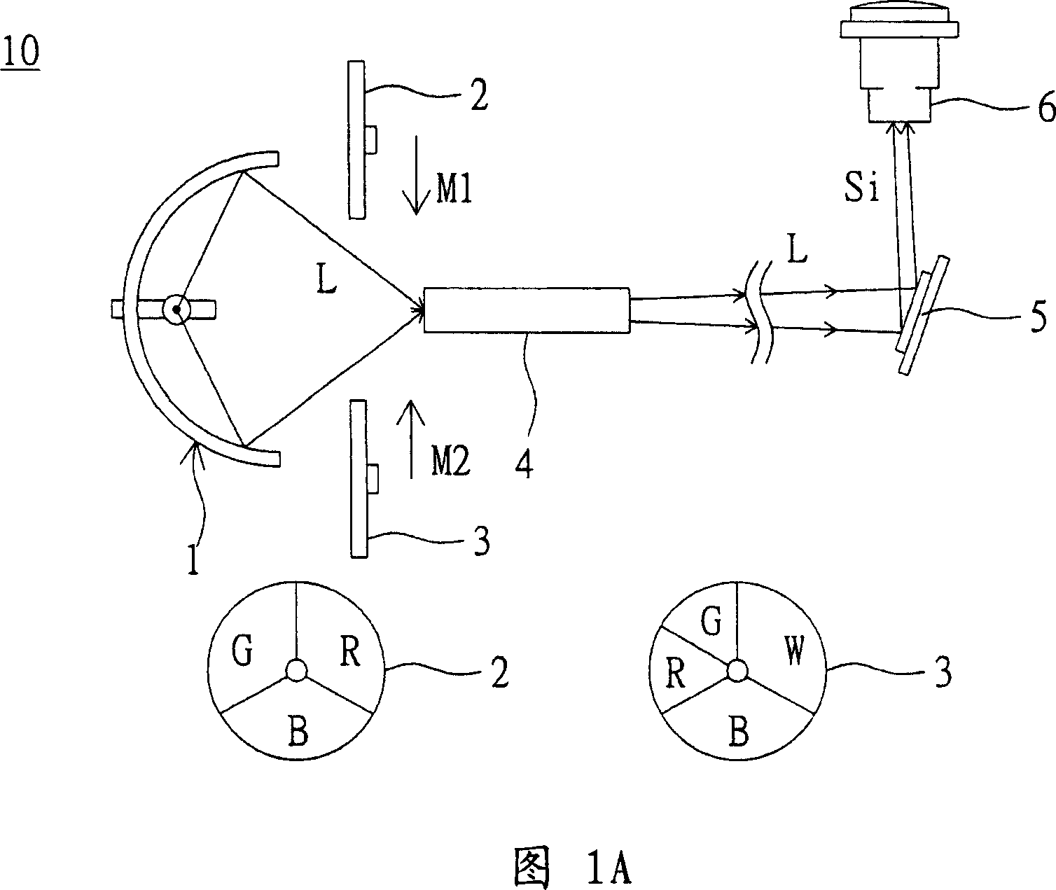
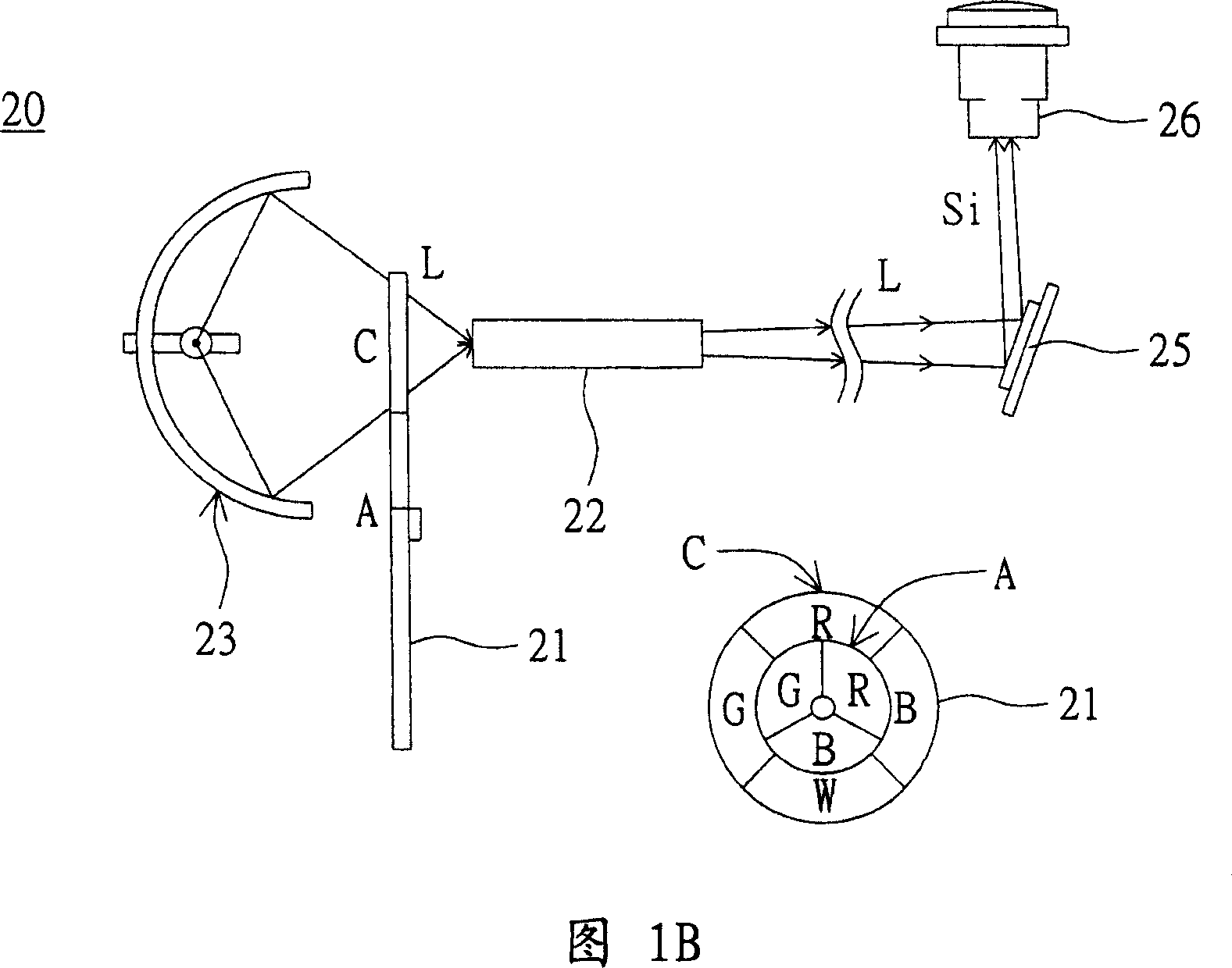
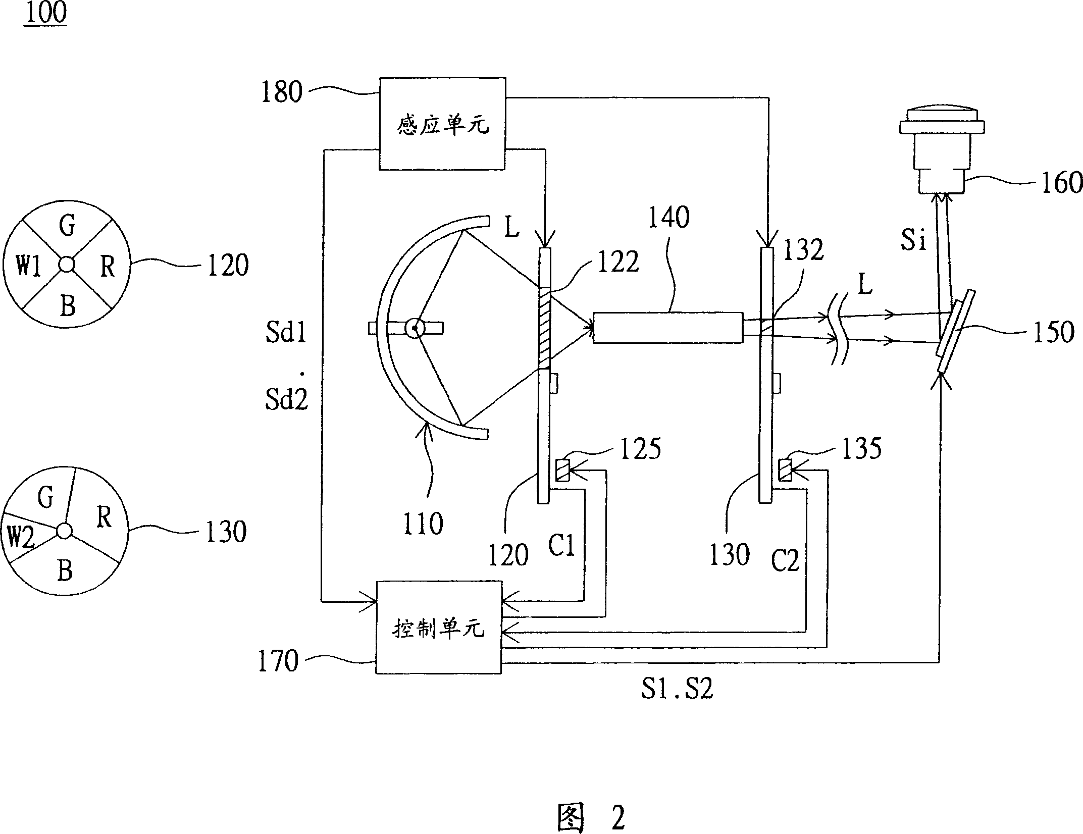
[0040] The present invention proposes a projection device, wherein the first color wheel and the second color wheel are simultaneously arranged on the light path between the light source module and the light valve. The first color wheel and the second color wheel respectively have a first white area and a second white area with unequal areas. When operating in the first mode, the first color wheel is controlled to rotate until the first white area stops on the light path while the second color wheel is controlled to rotate, and the light valve is controlled to generate an image signal according to the electronic signal output by the second color wheel; When operating in the second mode, the second color wheel is controlled to rotate until the second white area stops on the light path, while the first color wheel is controlled to rotate, and the light valve is controlled to generate image signals according to the electronic signal output by the first color wheel. Therefore, the...


PUM


Abstract

A projection unit is prepared for using light source module to provide an illumination light beam, setting both the first and the second colored wheels on light path of illumination light beam, arranging the first white color region and the second white color region separately on the first and the second colored wheels, setting area of the first white color region to be different from that of second one, electric-coupling control unit with the first and the second colored wheels. Its switching-over method of operation mode is also disclosed.

Description

technical field [0001] The present invention relates to a projection device and its operation mode switching method, in particular to a projection device capable of generating at least two operation modes and its operation mode switching method. Background technique [0002] Generally, single-chip digital light processing (digital light processing, DLP) technology projectors use a color wheel (color wheel, CW) to combine red light (red, R), green light (green, G), blue light (blue, B) Time-sharing and sequential input to digital micromirror devices (digital micromirror device, DMD) to generate color and brightness. However, because R, G, and B are not cast to DMD at the same time, the brightness cannot be improved. The traditional improvement method is to set a white (W) area in the color wheel to increase brightness, but the color saturation after color mixing is not as good as the color wheel composed of pure R, G, and B areas. In order to meet different usage requiremen...

Claims


Application Information

Patent Timeline
Patent Type & Authority Applications(China)
IPC IPC(8): G03B21/14G03B21/00H04N9/31
Inventor 王思克
Owner CORETRONIC
Why Eureka
Try Eureka