
Peripheral device detecting system and its method

A peripheral device and detection system technology, applied in the direction of instruments, electrical digital data processing, etc., can solve problems such as identification errors, undetectable printers, and incomplete contact

Inactive Publication Date: 2007-10-10
QUANTA COMPUTER INC
View PDF0 Cites 0 Cited by
  • Summary
  • Abstract
  • Description
  • Claims
  • Application Information

AI Technical Summary

Problems solved by technology

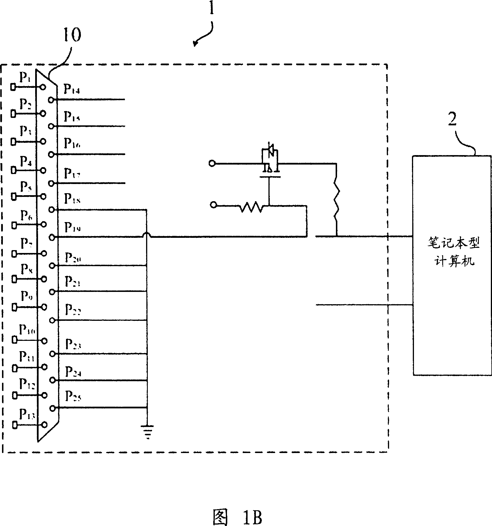
[0004] However, when the 19th pin of the printer cable and the 19th pin P of the printer connection port 10 19 When in contact, the other leads of the printer cable may not be in full contact with the other leads of the printing connection port 10, so that the printer cannot be detected by the notebook computer 2, resulting in an identification error

Method used


Image

  • Peripheral device detecting system and its method
  • Peripheral device detecting system and its method
  • Peripheral device detecting system and its method

Examples


Embodiment Construction

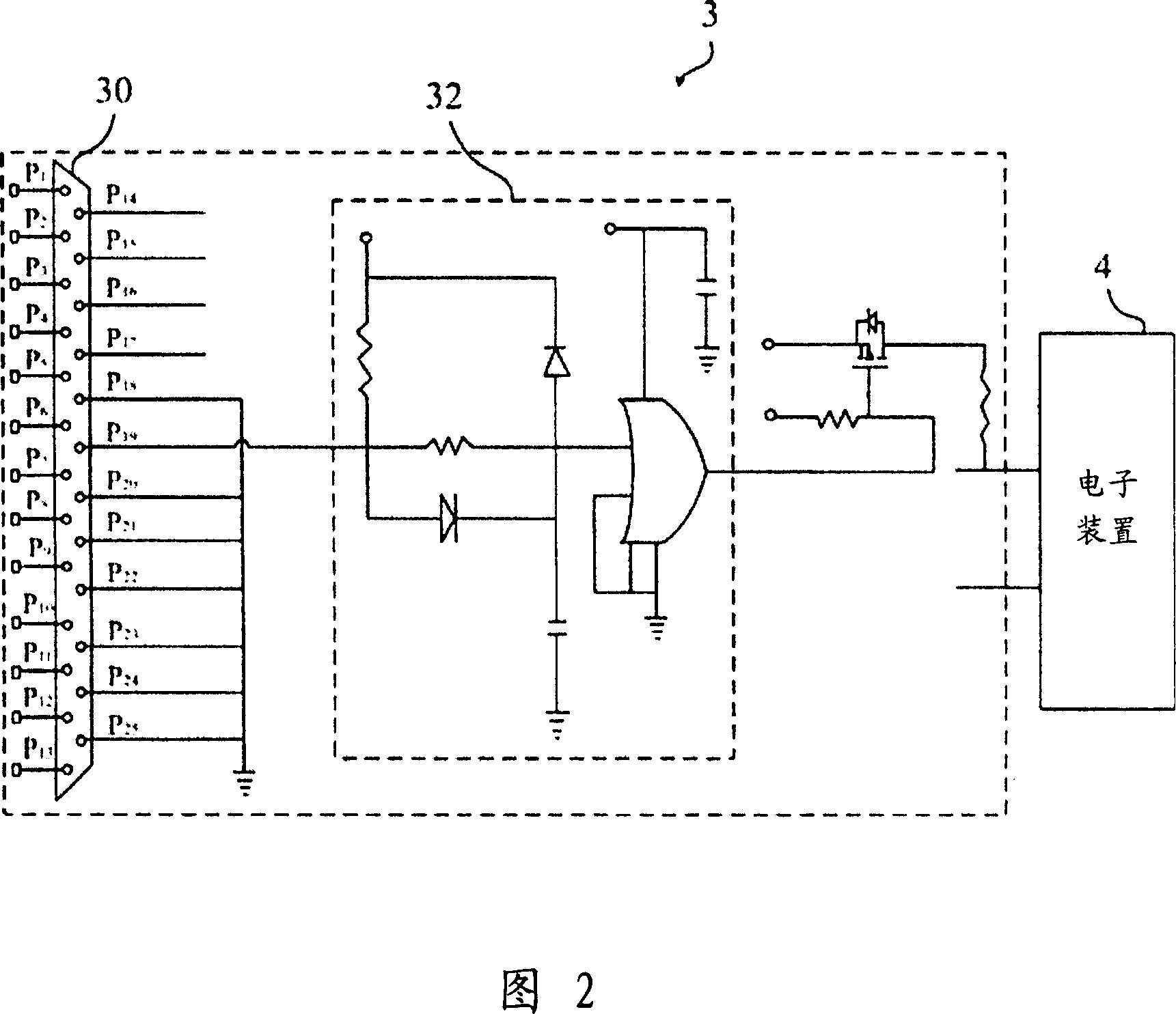
[0020] Please refer to FIG. 2 . FIG. 2 is a schematic circuit diagram illustrating the connection between the peripheral device detection system 3 and the electronic device 4 according to a preferred embodiment of the present invention. The peripheral device detection system 3 of the present invention is used to detect peripheral devices (Peripheral devices) (not shown in the figure) installed in electronic devices (Electronic apparatus) 4, such as printers (Printer), scanners (Scanner), etc. . In this embodiment, the peripheral device detection system 3 is set in an expansion base (not shown in the figure), and the expansion base is used to provide a peripheral connection port (Port) of the electronic device 4 to install other peripherals. device. In this embodiment, the electronic device 4 is a notebook computer (Notebook), and the peripheral device is a printer. The printer includes a cable, and the cable has 25 first pins, wherein the first detection pin is selected from...


PUM


Abstract

A detection system of peripheral device is prepared for arranging M numbers of the second lead wires on connection port as each second lead wire being separately corresponded to one of the first lead wires of cable, forming M numbers of the second load wires by grounded second detection load wires, generating voltage signal by responding the first detection lead wire with the second one, using delay circuit to receive voltage signal and outputting delayed voltage signal to electronic unit being used to start up detection on peripheral device.

Description

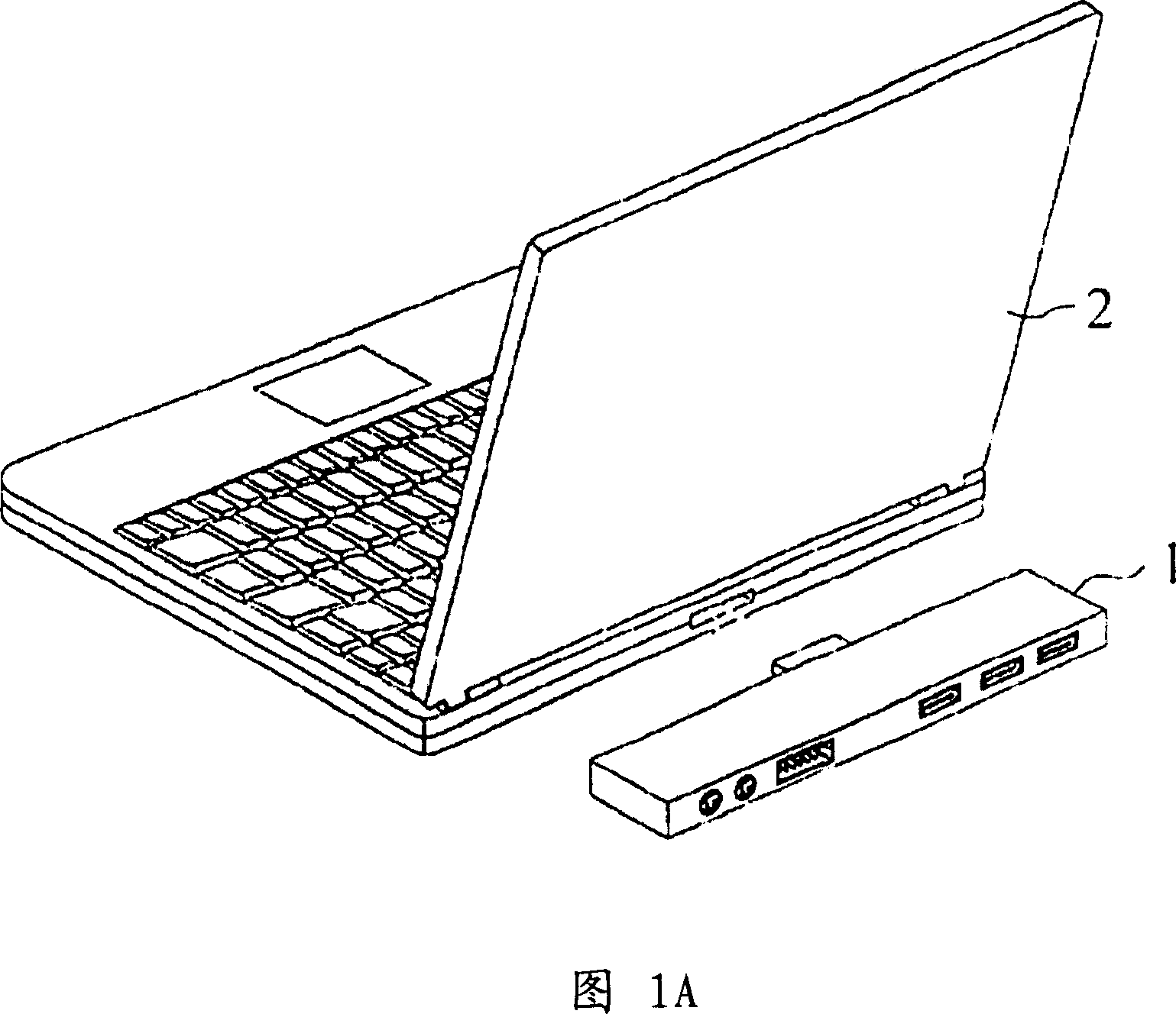
technical field [0001] The present invention relates to a peripheral device detection system and method thereof, and in particular to a peripheral device detection system and method thereof which allow the electronic device to normally detect the peripheral device each time the peripheral device is connected to the docking station of the electronic device. Background technique [0002] Please refer to FIG. 1A . FIG. 1A is an appearance view of a docking station 1 and a notebook computer (Notebook) 2 in the prior art. For now, although the notebook computer 2 has the convenience of being portable, its function is not as good as that of a desktop computer (Desktop). Therefore, an expansion base (Docking station) 1 has been developed to provide a rich peripheral connection port (Port) of the notebook computer 2, so as to install other peripheral devices (Peripheral devices), such as a printer (Printer), a scanner ( Scanner) and so on. [0003] Please refer to FIG. 1B . FIG. 1...

Claims


Application Information

Patent Timeline
Patent Type & Authority Applications(China)
IPC IPC(8): G06F13/40
Inventor 朱柄贤林恩贤
Owner QUANTA COMPUTER INC
Learn More