Artificial vibrator

A vibrator and sliding hole technology, which is applied in the direction of electric components, mechanical energy control, electrical components, etc., can solve the problems that the permanent magnet cannot move, the simulation accuracy is not high, and the vibration device cannot simulate vibration, so as to overcome the directionality and strength of vibration no clear effect

Inactive Publication Date: 2007-10-10
吴志恒
View PDF1 Cites 13 Cited by
  • Summary
  • Abstract
  • Description
  • Claims
  • Application Information

AI Technical Summary

Problems solved by technology

[0002] Currently used in the field of video games and other simulation equipment, the vibrator mainly uses a motor with an eccentric wheel, and the unbalanced rotation of the motor is used to generate vibration during power supply. The vibration of this kind of device is non-directional, it cannot show obvious collision effect, the vibration effect is poor, the simulation ability is low, and it cannot make people feel the realistic effect.
Chinese patent application number 200410008703.5 discloses a reciprocating vibrating device. Its structure is that coils are installed at both ends of the housing, and a permanent magnet is installed in the housing. The permanent magnets are used to hit the coils at both ends of the housing to express the collision effect. Although the vibration direction and the vibration effect have been improved, there are also the following disadvantages: since there is no connecting device between the permanent magnet and the housing, the vibration device cannot send out vibration when the permanent magnet is not in contact with the two ends of the housing. Vibration, so the vibration device can not simulate slight vibration, the simulation accuracy is not high; also because there is no connection device between the permanent magnet and the shell, so in the non-working state, the permanent magnet can be in any position in the shell, so in Under the action of external force during transportation, the permanent magnet will collide with the housing to make noise, and even damage the vibration device
In addition, since there are coils at both ends of the casing, the phase requirements for the control circuit to provide current signals to the two coils are greatly increased. If the phases are inconsistent, the efficiency of electric energy will be reduced. If the phases are opposite, the magnetic force generated by the coils at both ends is just right. In contrast, permanent magnets cannot move, thus greatly increasing the cost of the control circuit

Method used


Image

  • Artificial vibrator
  • Artificial vibrator
  • Artificial vibrator

Examples


Embodiment Construction

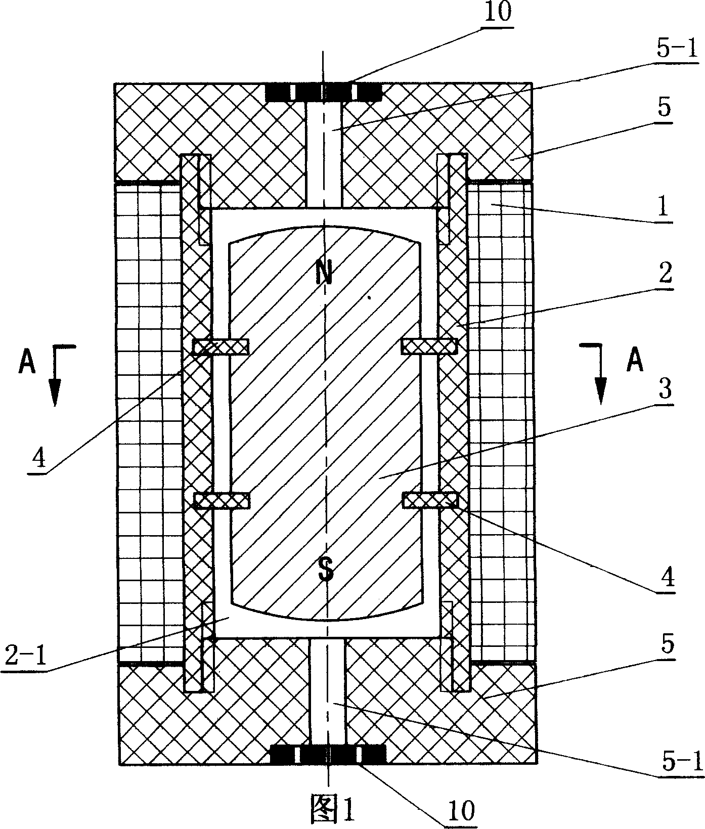
[0012] Embodiments are given below in conjunction with the accompanying drawings, and the present invention is further described in detail.

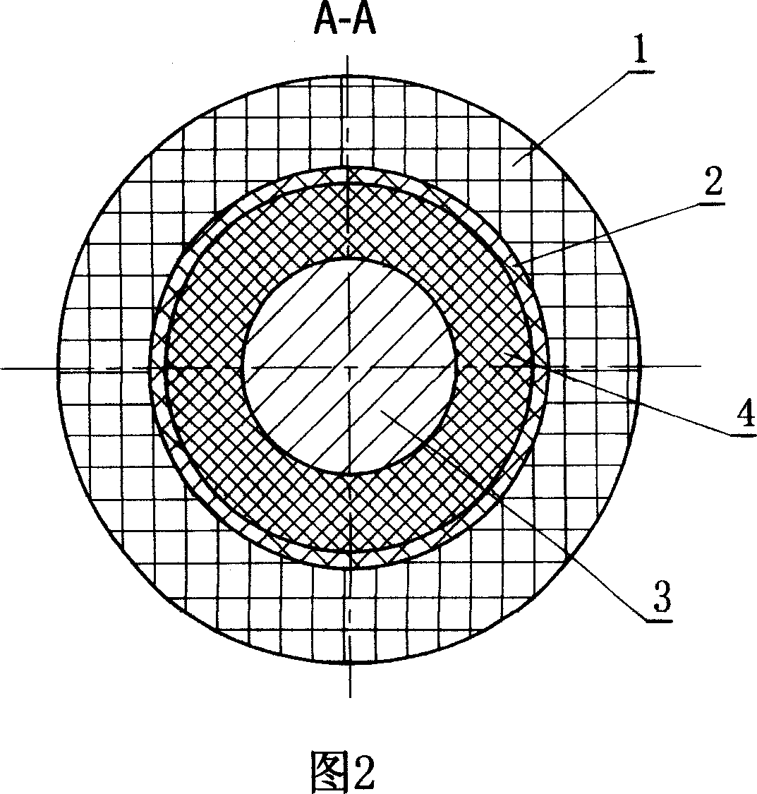
[0013] As shown in Figures 1 and 2, it is the first embodiment of the simulated vibrator of the present invention. A simulated vibrator includes a housing 2, a coil 1 and a magnetic hammer 3. The coil 1 rests on the housing 2, and the magnetic The hammer 3 is installed in the inner cavity 2-1 of the housing 2, the magnetic hammer 3 is flexibly connected with the housing 2 through the elastic member 4, and the two ends of the housing 2 are equipped with end caps 5, when the magnetic hammer 3 reciprocates, it can The end cap 5 contacts.

[0014] As shown in FIGS. 1 and 2 , the coil 1 surrounds the outer wall of the housing 2 around the central axis of the cylindrical portion of the housing 2 . The coil 1 can also conform to the inner wall of the cylindrical part of the housing 2 .

[0015] As shown in Figures 1 and 2, the magnetic hammer...


PUM


Abstract

Being applicable to apparatus in video game, simulated training, motion effect cinema, and the simulated vibrator includes shell, winding, and magnetic hammer. The shell supports winding. The magnetic hammer is installed in cavity of the shell. Through elastic piece, the magnetic hammer is connected to the shell body flexibly. End plates are installed on two ends of the shell body. When doing reciprocal motion, the magnetic hammer contacts end plates or vibration transmission pieces. Advantages are: directivity of vibration, high simulation capability, and obvious collision effect, vivid effect. When multiple simulated vibrators are utilized together can simulate most of vibration situation in reality.

Description

technical field [0001] The invention relates to a vibrator, which is mainly used for video games, simulation training, dynamic cinema and other equipment. Background technique [0002] Currently used in the field of video games and other simulation equipment, the vibrator mainly uses a motor with an eccentric wheel. When the power is supplied, the unbalanced rotation of the motor is used to generate vibration. The vibration of this device has no directionality and cannot show obvious collision effects. , the vibration effect is poor, the simulation ability is low, and it cannot make people feel the realistic effect. Chinese patent application number 200410008703.5 discloses a reciprocating vibrating device. Its structure is that coils are installed at both ends of the housing, and a permanent magnet is installed in the housing. The permanent magnets are used to hit the coils at both ends of the housing to express the collision effect. Although the vibration direction and th...

Claims


Application Information

Patent Timeline
Patent Type & Authority Applications(China)
IPC IPC(8): H02K7/065
Inventor 吴志恒
Owner 吴志恒
Why Eureka
Try Eureka