Decoder and relative method

A decoding device and decoder technology, applied in the field of soft-decision decoding devices, can solve the problem that the advantages of soft-decision decoders cannot be fully utilized

Inactive Publication Date: 2007-10-10
REALTEK SEMICON CORP
View PDF0 Cites 2 Cited by
  • Summary
  • Abstract
  • Description
  • Claims
  • Application Information

AI Technical Summary

Problems solved by technology

In this case, the quantized signal generated is likely to be concentrated in some levels, while other levels are useless, in other words, the advantages of the subsequent soft decision decoder cannot be fully utilized

Method used


Image

  • Decoder and relative method
  • Decoder and relative method
  • Decoder and relative method

Examples


Embodiment Construction

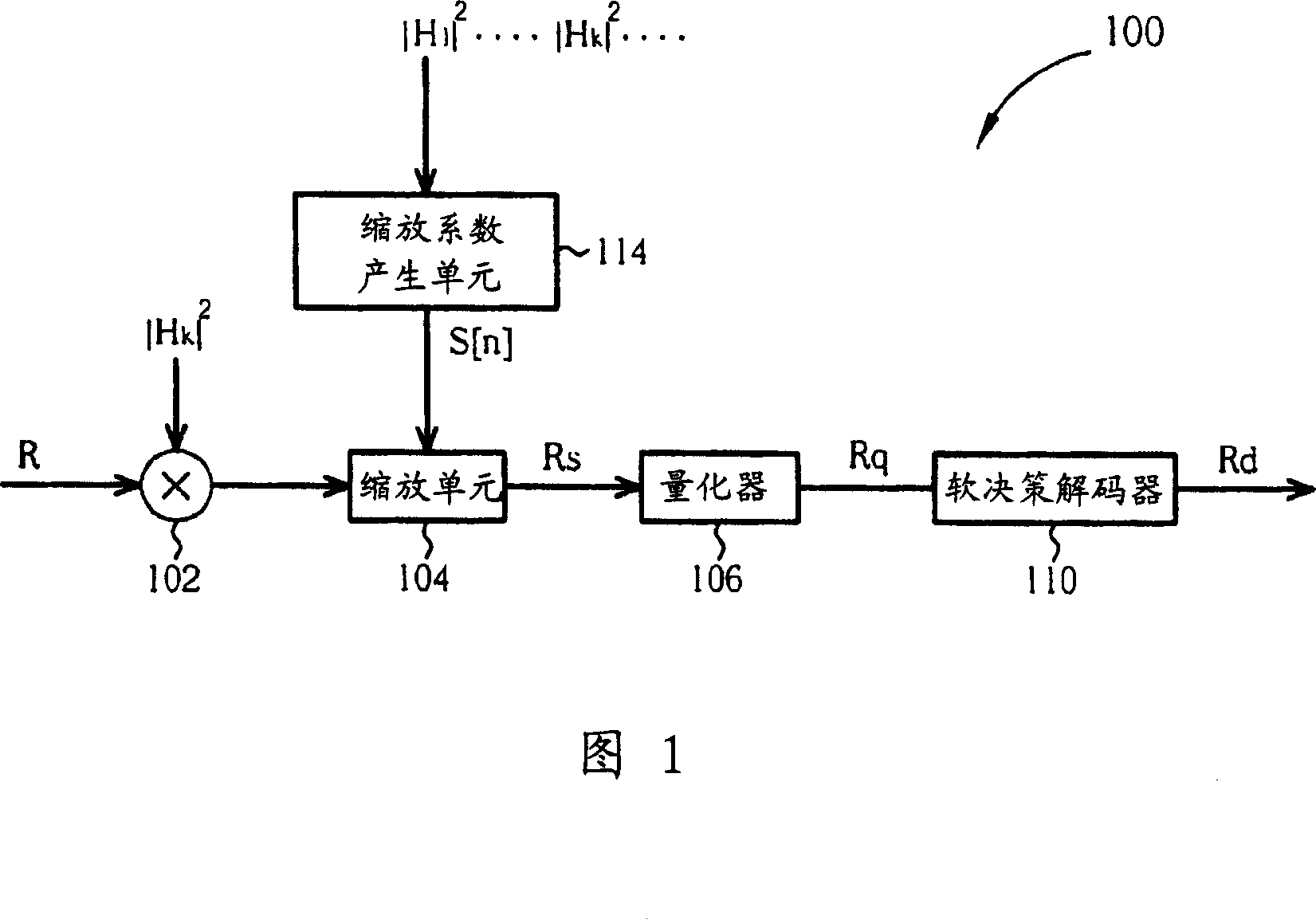
[0014] Please refer to FIG. 1 , which is a schematic diagram of a first embodiment of a decoding device 100 of the present invention. In this embodiment, the decoding device 100 is applied to a multi-tone (multi-tone) system, for example: an orthogonal frequency division multiplexing (orthogonal frequency division multiplexing, OFDM) system, and the received signal R is a multi-tone signal, so the received signal R contains multiple sub-data transmitted by different sub-carriers respectively. Those familiar with communication technology should also understand that the technology described in the following embodiments of the present invention can also be used in other communication systems, whether wired or wireless, and not limited to OFDM systems. As shown in FIG. 1 , the decoding device 100 includes a channel response compensation unit 102 , a scaling unit 104 , a quantizer 106 , a soft decision decoder 110 and a scaling factor generating unit 114 . First, the channel respo...


PUM


Abstract

The decoding unit includes following parts: using scaling coefficient, the scaling unit adjusts received signal in order to output scaled signal; being coupled to the scaling unit, the quantizer is in use for quantizing the scaled signal to generate quantized signal; being coupled to the quantizer, the soft decision decoder is in use for decoding the quantized signal to generate decoded signal; being coupled to the scaling unit, a scaling coefficient generation unit is in use for generating the scaling coefficient based on system information of the decoding unit.

Description

technical field [0001] The present invention provides a decoding device and a related method, especially a soft decision decoding device and a related method. Background technique [0002] The main difference between soft decision (soft decision) decoder and hard decision (hard decision) decoder is that if the amount of data carried by a received signal is one bit, for example, when the signal value of the received signal is 1 or -1, It can respectively represent that the bit is 1 or 0, then the hard decision decoder represents the received signal with only one bit, while the soft decision decoder represents the received signal with more than two bits. Due to the attenuation of the received signal by the communication channel, the signal value of the received signal may be 0.8, 0.65 or -0.7 in actual situations. Therefore, the front end of the hard decision decoder usually needs to add a slicer (slicer ) to judge a received signal value greater than zero as 1 and a received...

Claims


Application Information

Patent Timeline
IPC IPC(8): H03M7/30
Inventor 卓俊铭王承康李亮辉颜光裕
Owner REALTEK SEMICON CORP
Why Eureka
Try Eureka