Optical fiber coupling semiconductor laser

A fiber-coupled, semiconductor technology, applied in the field of fiber-coupled semiconductor lasers, can solve problems such as low power density and single wavelength, and achieve the effect of increasing optical power density and achieving high-brightness output

Pending Publication Date: 2021-12-14
HANS LASER TECH IND GRP CO LTD
View PDF11 Cites 0 Cited by
  • Summary
  • Abstract
  • Description
  • Claims
  • Application Information

AI Technical Summary

Problems solved by technology

[0005] The technical problem to be solved by the embodiment of the present application is that the existing fiber-coupled semiconductor laser has the problem of single wavelength and low power density

Method used


Image

  • Optical fiber coupling semiconductor laser
  • Optical fiber coupling semiconductor laser
  • Optical fiber coupling semiconductor laser

Examples


Embodiment 1

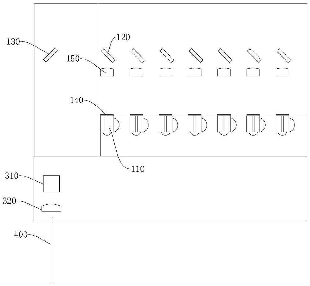
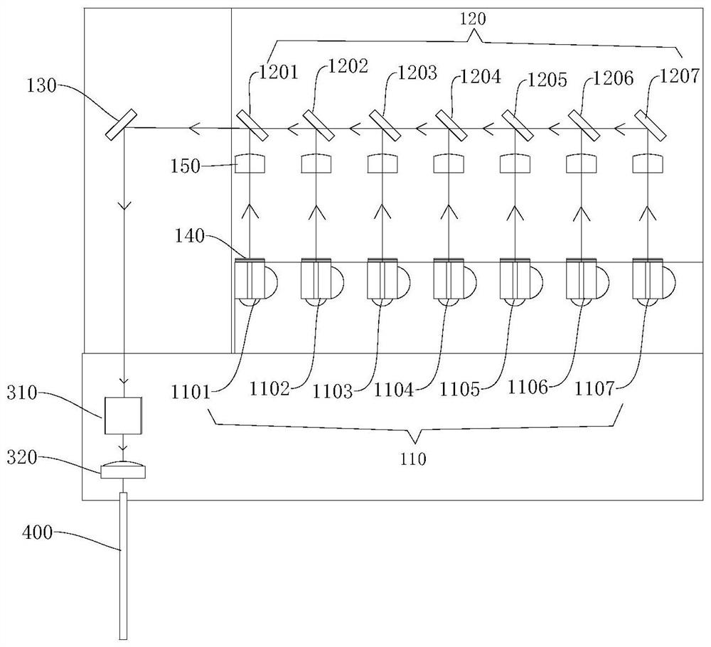
[0071] refer to Figure 1 to Figure 3 , the fiber-coupled semiconductor laser is provided with a laser module, a focusing system and an optical fiber 400 .

[0072] The laser module is provided with a light emitting unit group and a corresponding dichroic mirror group. A light-emitting unit group contains 7 light-emitting units 110 (N=7), which are the first laser chip 1101, the second laser chip 1102, the third laser chip 1103, the fourth laser chip 1104, the fifth laser chip 1105, the Six laser chips 1106 and seventh laser chips 1107. A dichroic mirror group includes 7 dichroic mirrors, namely the first dichroic mirror 1201 corresponding to the first laser chip 1101 and the second dichroic mirror 1202 corresponding to the second laser chip 1102 , the third dichroic mirror 1203 corresponding to the third laser chip, the fourth dichroic mirror 1204 corresponding to the fourth laser chip, the fifth dichroic mirror corresponding to the fifth laser chip 1205. A sixth dichroic ...

Embodiment 2

[0084] refer to Figure 4 to Figure 7 , the fiber-coupled semiconductor laser is equipped with 8 laser modules, a focusing system and an optical fiber 400. The 8 laser modules are respectively the first laser module A, the second laser module B, the third laser module C, and the fourth laser module Module D, fifth laser module E, sixth laser module F, seventh laser module G, eighth laser module H.

[0085] Among them, 8 laser modules are evenly arranged in two rows, and each row is 4 laser modules (that is, M=4), that is, the first laser module A, the third laser module C, the fifth laser module E and The seventh laser module G is located in the same row, and respectively located on 4 steps with decreasing heights. The second laser module B, the fourth laser module D, the sixth laser module F and the eighth laser module H are located in the same row, and are respectively located on four steps with decreasing heights. The first laser module A and the second laser module B are...


PUM


Abstract

The embodiment of the invention belongs to the technical field of semiconductor lasers, and relates to an optical fiber coupling semiconductor laser. The optical fiber coupling semiconductor laser comprises a laser module, a focusing system and an optical fiber, the laser module comprises a light-emitting unit group and a first optical element group, the light-emitting unit group comprises N light-emitting units emitting laser beams with different wavelengths, and the N light-emitting units in the same group are located on the same plane; the first optical element group comprises N first optical elements capable of reflecting the laser with the specific wavelength, the first optical elements and the light emitting units are arranged in a one-to-one correspondence mode, the N first optical elements are arranged in the reflection direction of the laser beams, and the first optical elements can transmit the laser beams reflected by the first optical elements in the same group; and the focusing system and the optical fiber are sequentially arranged on an emergent light path of the multi-wavelength laser. According to the technical scheme provided by the invention, N laser beams with different wavelengths can enter the optical fiber together, so that high-power density output is realized.

Description

technical field [0001] The present application relates to the technical field of semiconductor lasers, and more specifically, to a fiber-coupled semiconductor laser. Background technique [0002] Semiconductor lasers have been widely used in the fields of laser communication, optical storage, optical gyroscope, laser printing, ranging and radar. The fiber-coupled semiconductor laser is an industrial machine that injects the laser light emitted from the semiconductor laser into the optical fiber, and outputs the laser light from the optical fiber. [0003] Fiber-coupled semiconductor lasers have the advantages of small size and high electro-optical conversion efficiency. They are often used directly in industrial, medical, military and other fields, and are also often used as pump sources for fiber lasers. With the development of industry, there are higher requirements for the miniaturization, high power and high power density, high conversion efficiency, and wavelength dive...

Claims


Application Information

Patent Timeline
Patent Type & Authority Applications(China)
IPC IPC(8): H01S5/40H01S5/02251H01S5/02253H01S5/02255G02B6/42G02B27/10
CPCH01S5/02251H01S5/02253H01S5/02255H01S5/4012H01S5/4087G02B6/4206G02B6/4214G02B27/1006
Inventor 罗又辉郝明明张增斌林炳创李雅王瑾高云峰
Owner HANS LASER TECH IND GRP CO LTD
Why Eureka
Try Eureka