Method and device for layout mobile radio sensor network node based on virtual force

A sensor node, sensor network technology, applied in data exchange networks, transmission systems, digital transmission systems, etc., can solve problems such as limited application scope and application effects

Inactive Publication Date: 2007-10-10
ZHEJIANG UNIV
View PDF0 Cites 29 Cited by
  • Summary
  • Abstract
  • Description
  • Claims
  • Application Information

AI Technical Summary

Problems solved by technology

[0009] These methods have achieved certain results, but as far as the current research progress is concerned, there is no layout method that comprehensively considers the influence of the position of the target

Method used


Image

  • Method and device for layout mobile radio sensor network node based on virtual force
  • Method and device for layout mobile radio sensor network node based on virtual force
  • Method and device for layout mobile radio sensor network node based on virtual force

Examples


Embodiment Construction

[0049] The present invention will be further described below in conjunction with drawings and embodiments.

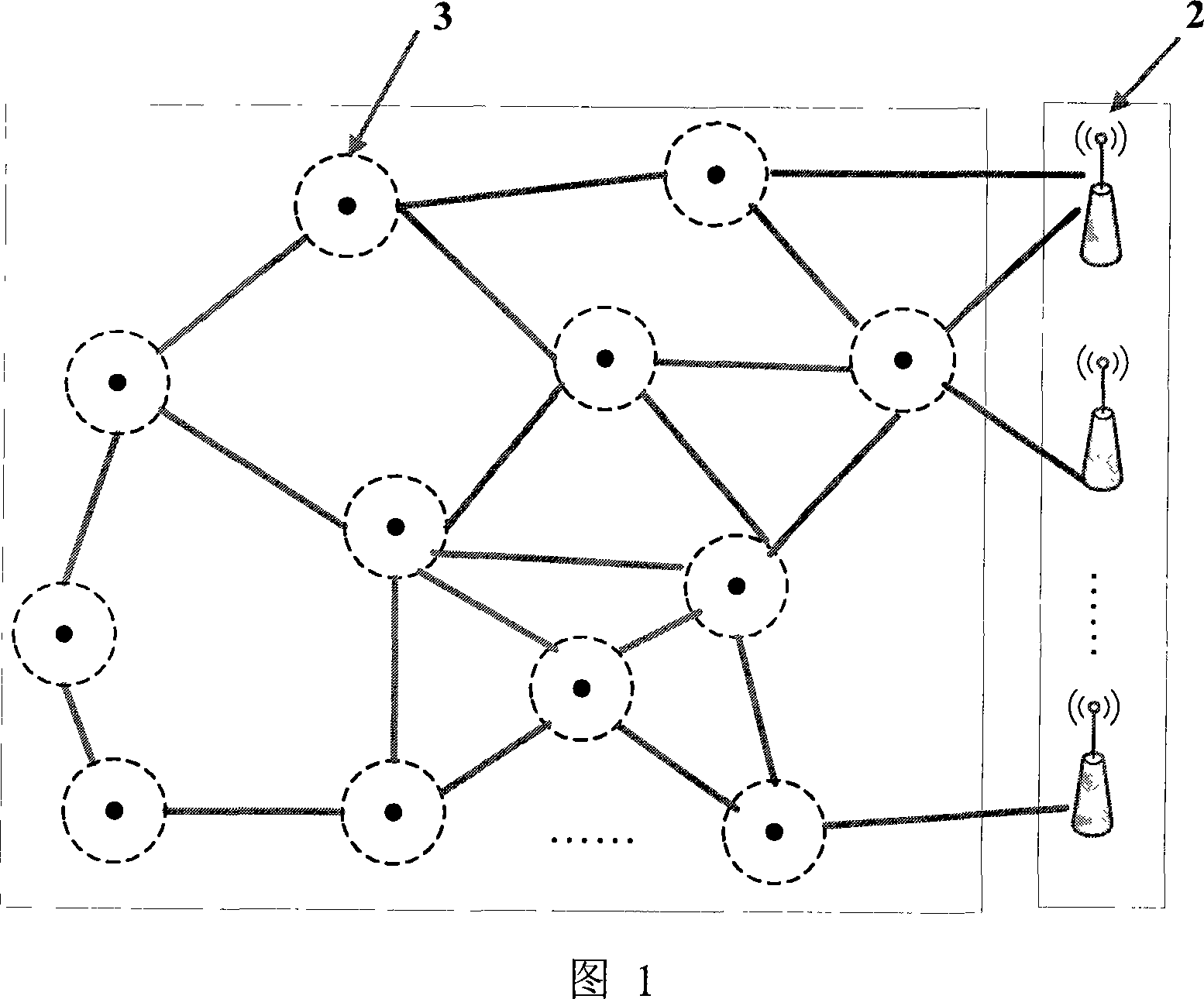
[0050] FIG. 1 is a schematic diagram of a node layout of a mobile wireless sensor network according to the present invention, which includes M convergence nodes 2 and N mobile wireless sensor nodes 3 . The M aggregation nodes, the N mobile wireless sensor nodes, and the M aggregation nodes and the N mobile wireless sensor nodes are connected through a wireless network.

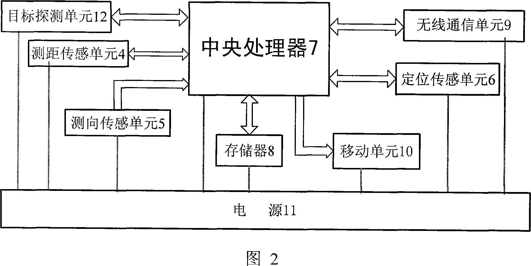
[0051] Each mobile wireless sensor node 3 (as shown in Figure 2) includes a central processing unit 7, a memory 8, a distance sensing unit 4, a direction finding sensing unit 5, a positioning sensing unit 6, a wireless communication unit 9, a mobile unit 10, power supply 11 and target detection unit 12, ranging sensor unit 4, direction finding sensor unit 5, mobile unit 10, positioning sensor unit 6, wireless communication unit 9, target detection unit 12 and memory 8 communicate with central processing...


PUM


Abstract

The method comprises: estimating the direction and distance that the sensor node should be moved by calculating the size and direction of virtual force loaded by each sensor node; driving the sensor node to make relevant movement until reaching a force-balanced point-namely realizing a distribution of sensor network node. By the invention, the sensor nodes can automatically move according to its located geographical environment.

Description

technical field [0001] The invention relates to the field of wireless sensor networks, in particular to a node layout method and device for a mobile wireless sensor network based on virtual force. Background technique [0002] Wireless sensor network is an emerging hot technology, which has been highly valued by industry and academia in recent years. In a wireless sensor network, it usually includes M sink nodes and N mobile wireless sensor nodes, M and N are positive integers respectively, between M sink nodes, between N mobile wireless sensor nodes, and between M sink nodes and N mobile The wireless sensor nodes are connected through the wireless network. [0003] Sensor network layout is a basic issue in the field of sensor networks, which will directly affect the performance and life cycle of sensor networks. However, since the sensor network often works in an unknown, complex or even hostile environment, its layout is almost impossible to complete manually. Therefore,...

Claims


Application Information

Patent Timeline
IPC IPC(8): H04L12/28H04L12/24
Inventor 吴朝晖李石坚夏明望
Owner ZHEJIANG UNIV
Why Eureka
Try Eureka