
Speaker and method of producing the same

A speaker and resin-made technology, applied in the direction of sensors, electrical components, etc., can solve problems such as low sound pressure, magnetic influence, etc., achieve good performance, improve bonding strength, and achieve flattening effects

Inactive Publication Date: 2007-10-10
PANASONIC CORP
View PDF6 Cites 10 Cited by
  • Summary
  • Abstract
  • Description
  • Claims
  • Application Information

AI Technical Summary

Problems solved by technology

[0007] However, since the above-mentioned conventional loudspeaker is produced by bending a single piece of magnetic metal material to produce the yoke 11 constituting the magnetic circuit, a gap is formed at each corner of the rectangular yoke 11.
Therefore, flux leakage occurs from this gap, resulting in performance degradation such as a decrease in sound pressure due to a decrease in magnetic flux density.
In addition, the leaking magnetic gas may have an adverse effect on other electronic components densely packed around the speaker

Method used


Image

  • Speaker and method of producing the same
  • Speaker and method of producing the same
  • Speaker and method of producing the same

Examples


Embodiment approach 1

[0028] Hereinafter, the present invention will be described in conjunction with Embodiment 1.

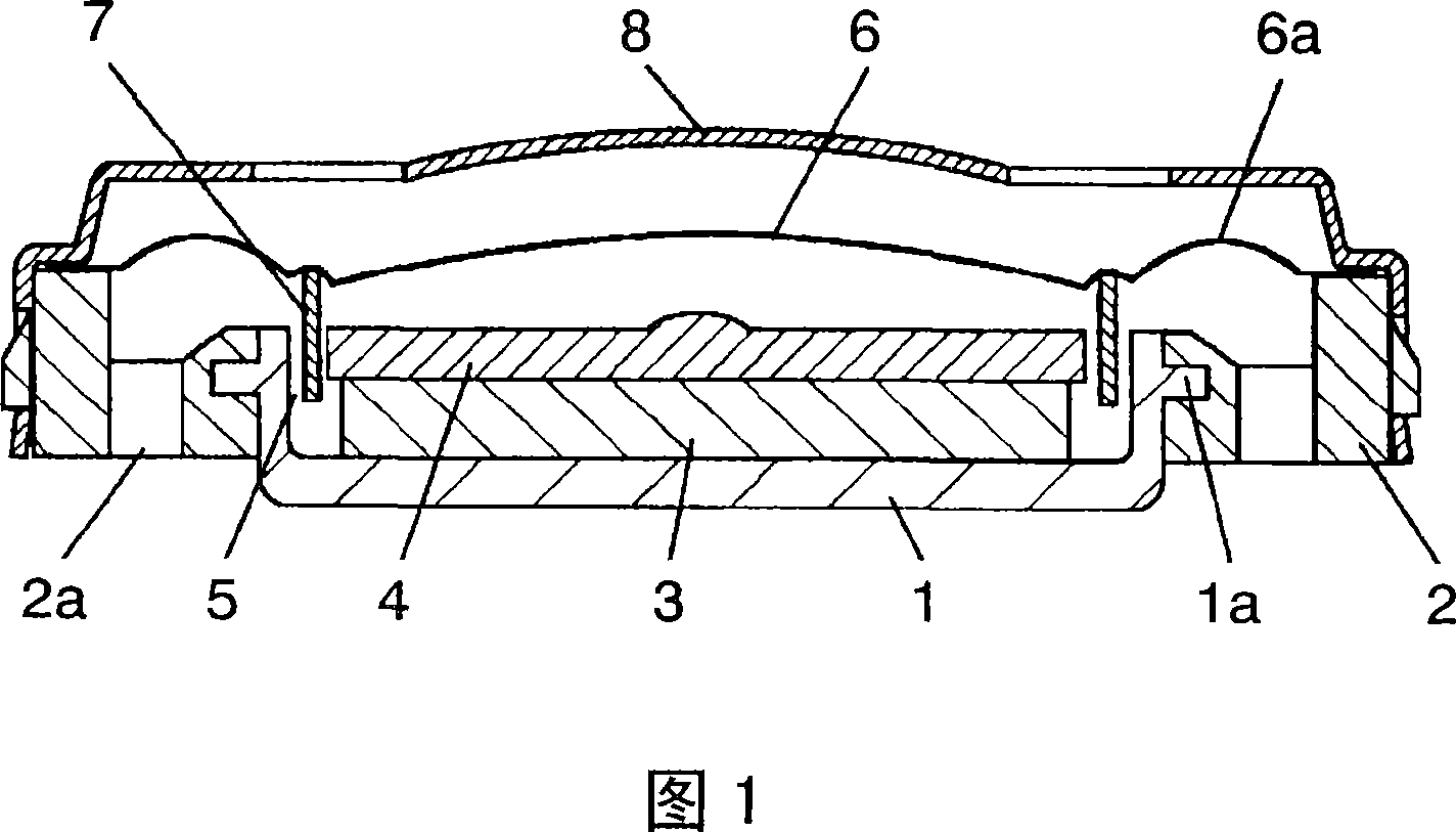
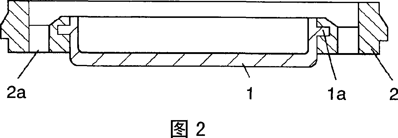
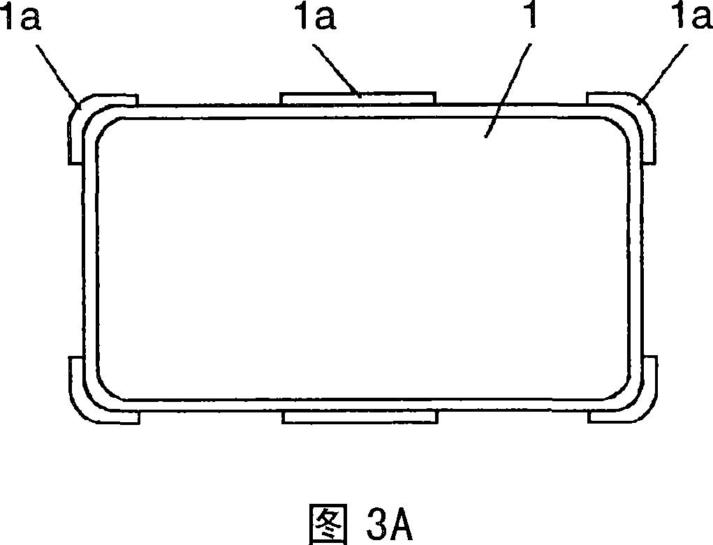
[0029] FIG. 1 is a cross-sectional view showing the structure of a loudspeaker manufactured by a loudspeaker manufacturing method according to Embodiment 1 of the present invention. Fig. 2 is a cross-sectional view showing a frame on which a yoke is insert-molded to be used in the speaker. 3A, 3B, and 3C are a plan view, a front sectional view, and a side sectional view showing a yoke used in the speaker, respectively. In FIG. 1 , FIG. 2 , FIG. 3A , FIG. 3B , and FIG. 3C , the yoke body 1 is formed into a rectangular plate shape using a magnetic metal material. In addition, tongue-shaped flange portions 1 a are symmetrically provided on each corner portion and long side of the yoke body 1 , and the flange portions 1 a protrude outward from a position lowered by a predetermined dimension from the upper end surface of the yoke body 1 . By providing a collar portion at a position low...

Embodiment approach 2

[0040] Next, the present invention will be described in conjunction with Embodiment 2.

[0041] In Embodiment 2, the structure of the voice coil used in the speaker of Embodiment 1 is different. Since the configuration other than this is the same as that of Embodiment 1, the same reference numerals are assigned to the same parts, and detailed description thereof will be omitted. Hereinafter, only different parts will be described with reference to the drawings.

[0042] 5 is a cross-sectional view showing the structure of a speaker manufactured by the speaker manufacturing method according to Embodiment 2 of the present invention. In FIG. 5 , the voice coil 9 is constituted by forming coils of a predetermined pattern in a coiled state on the front and back sides of a resin base material.

[0043]The center of the diaphragm 10 with the edge 10a integrally provided on the periphery is bonded to the base material of the voice coil 9 except the coil, so that the voice coil 9 is a...


PUM


Abstract

A plate material is drawn into a rectangular plate shape and the peripheral edge of each corner is pressed. A yoke (1) is formed, and the yoke (1) has a tongue-like flange (1a) projecting outward from a position below an upper end surface by a predetermined dimension. A resin frame (2) is insert-molded so as to cover the flange (1a). A magnet (3) is joined to the inside of the yoke (1), and a magnetic circuit where a magnetic gap (5) is formed is produced. A diaphragm (6) to which a voice coil (7) is joined is joined to a frame (2). When a speaker is produced in this way, joining strength between the yoke (1) and the frame (2) is increased and the height of the speaker is reduced. Further, a gap is eliminated from each corner of the yoke (1), and the speaker is excellent both in quality and performance where there is no magnetic leakage.

Description

technical field [0001] The present invention relates to a small and thin rectangular speaker used in various audio equipment and information communication equipment, especially in applications such as mobile phones where it is difficult to secure a speaker installation space, and a manufacturing method thereof. Background technique [0002] With the development of miniaturization and multi-function of various audio equipment and information communication equipment, the speakers used in these equipment are also increasing more than before, and the miniaturization is developing, especially for the speakers used in mobile phones, not only It is required to be miniaturized, but also required to have high sound quality. Against such a background, as a speaker for mobile phones where it is difficult to secure a speaker installation space, from the viewpoint of utilizing the limited space more effectively, emphasis has been placed on the development of a rectangular speaker compare...

Claims


Application Information

Patent Timeline
IPC IPC(8): H04R9/02
Inventor 高濑智康榎本光高山崎一也久保和隆隅山昌英
Owner PANASONIC CORP
Learn More