Electromagnetic oven

A technology of induction cooker and furnace body, applied in the field of induction cooker, which can solve the problems of reduced service life, reduced service life, burnt pots and panels, etc., and achieves the effects of reducing temperature resistance requirements, reducing production costs, and ensuring temperature control accuracy

Inactive Publication Date: 2007-10-17
袁明
View PDF0 Cites 5 Cited by
  • Summary
  • Abstract
  • Description
  • Claims
  • Application Information

AI Technical Summary

Problems solved by technology

[0002] The widely used induction cooker basically installs the temperature sensing probe device on the lower surface of the panel. When in use, the pot is placed on the panel, and the bottom of the pot is directly in contact with the panel. When the electromagnetic wire generated by the coil under the panel passes through When the pot is made of ferromagnetic material, eddy current is generated at the bottom of the pot to generate heat, and the temperature detected by the temperature sensor device is the temperature after the heat generated at the bottom of the pot is conducted through the panel, so there are the following problems: 1. In terms of time late
Since the materials of the panel are mostly microcrystalline ceramics or glass, these materials are poor conductors of heat, and the heat generated at the bottom of the pot is detected by the temperature sensing probe device after being conducted by the poor conductor panel of heat, so that the detected temperature changes The temperature change relative to the bottom of the pan is delayed in time
2. The detected temperature has a large error compared with the temperature at the bottom of the pot
The heat generated at the bottom of the pot is detected by the temperature sensor device after it is conducted through the hot poor conductor panel. In the heating stage, the detected temperature is lower than the temperature at the bottom of the pot, plus the cooling fan in the furnace. , making the detected temperature lower, so the detected temperature has a larger error than the temperature at the bottom of the pot
3. The temperature inside the furnace is high
Due to the large error between the detected temperature and the temperature at the bottom of the pot and the delay in time, the constant temperature function of the constant temperature device cannot truly reflect the temperature at the bottom of the pot, which may cause the temperature at the bottom of the pot to be different from the temperature on the upper surface of the panel. Exceeding the set or allowable temperature range, thus burning the pan and panel
2. Reduced service life
Due to the high temperature in the furnace, the working environment of the electronic components in the furnace is deteriorated, so that the failure of electronic components increases and the service life decreases

Method used


Image

  • Electromagnetic oven
  • Electromagnetic oven
  • Electromagnetic oven

Examples


Embodiment Construction

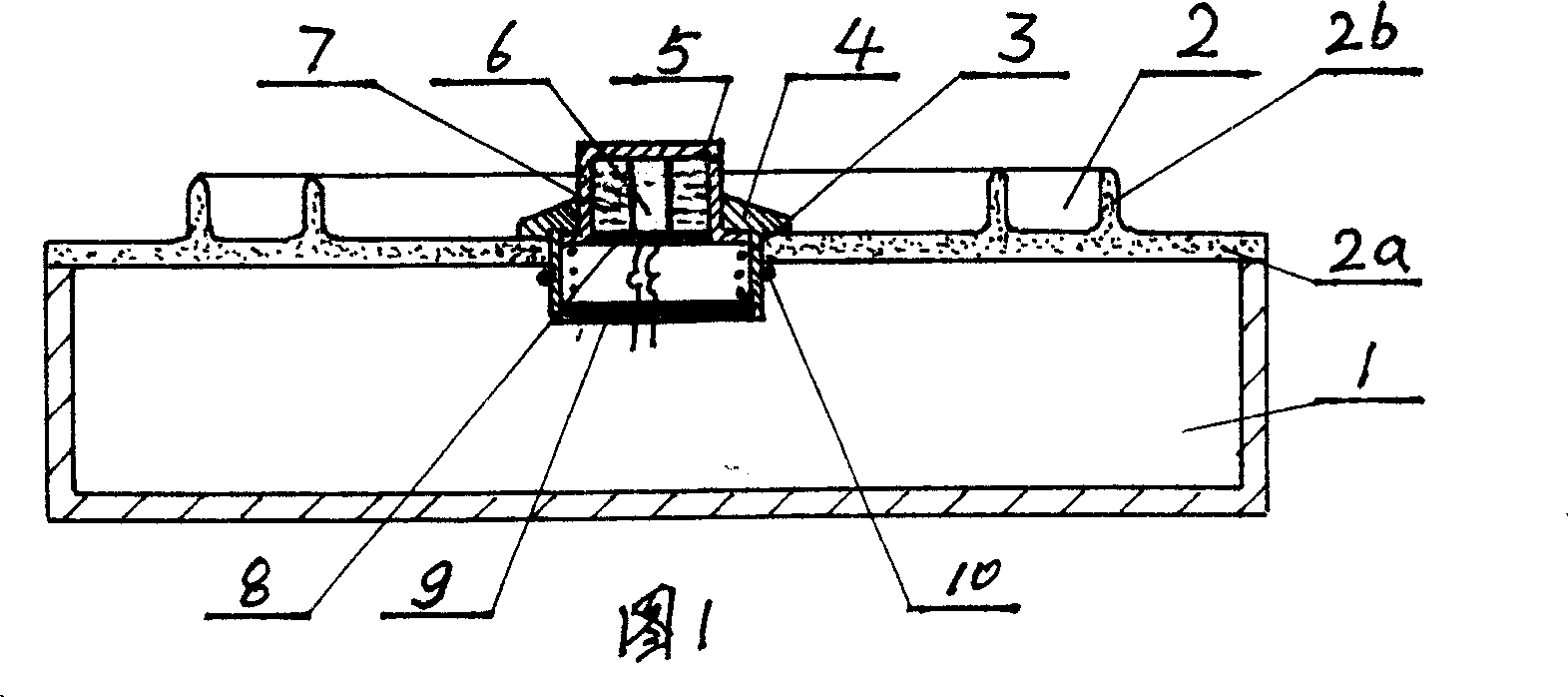
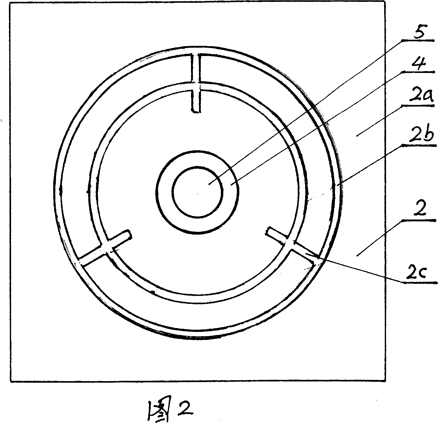
[0021] As shown in Fig. 1 and Fig. 2, a panel (2) is installed on the body of furnace (1), for the view can show the invention point of the present invention more clearly, omit in Fig. 1 and be installed in the body of furnace (1) The panel (2) consists of a panel body (2a), 2 closed concentric raised rings (2b) and 3 raised ribs (2c) designed on the panel body (2a), the 2 The height of the concentric raised ring (2b) is the same as the height of the three raised ribs (2c), and the temperature sensor body (4) installed on the panel body (2a) in the raised ring (2b) passes through the fixing device (10) fixing, the fixing device (10) is the structural form of snap ring, also can use the structural form of screw thread, in the endoporus of this temperature sensing probe device body (4), be equipped with temperature sensing cap (5), temperature sensing The cap (5) is in the form of a closed upper end and surrounding wall, and an open lower end, which can slide relative to the bod...


PUM


Abstract

The invention discloses an induction cooker which includes body 1, panel 2 equipped on the body 1, temperature probe device equipped on the panel 2 and which includes temperature probe body 4 and probe cap 5 and so on, wherein the probe cap 5 can slide in relation to the temperature probe body 4, and temperature probe 6 and heat conduction silica gel 7 are installed in the probe cap. The panel includes panel body 2a, protruding ring 2b and protruding rib 2c, and the temperature probe device is mounted on the panel body 2a in the protruding ring 2a, therefore, the temperature probe device can directly contact with pan bottom thereby accurately and quickly detecting the temperature of the pan bottom, and can reduce the cooker temperature thereby improving working condition for electronic element then prolonging service life.

Description

technical field [0001] The invention relates to an electromagnetic cooker, in particular to an electromagnetic cooker in which a temperature-sensing probe device can ensure direct contact with the bottom of a pan in a use state. Background technique [0002] The widely used induction cooker basically installs the temperature sensing probe device on the lower surface of the panel. When in use, the pot is placed on the panel, and the bottom of the pot is directly in contact with the panel. When the electromagnetic wire generated by the coil under the panel passes through When the pot is made of ferromagnetic material, eddy current is generated at the bottom of the pot to generate heat, and the temperature detected by the temperature sensor device is the temperature after the heat generated at the bottom of the pot is conducted through the panel, so there are the following problems: 1. In terms of time later. Since the materials of the panel are mostly microcrystalline ceramic...

Claims


Application Information

Patent Timeline
Patent Type & Authority Applications(China)
IPC IPC(8): F24C7/00F24C7/08
Inventor 袁明
Owner 袁明
Why Eureka
Try Eureka