Measuring system with at least one sensor line

A measurement system and sensor technology, applied in the field of measurement systems, can solve the problems of high design cost and difficult connection of measurement system control units.

Inactive Publication Date: 2007-10-17
DR JOHANNES HEIDENHAIN GMBH
View PDF3 Cites 6 Cited by
  • Summary
  • Abstract
  • Description
  • Claims
  • Application Information

AI Technical Summary

Problems solved by technology

[0006] A disadvantage in the case of such a measuring system is thus that in order to connect the measuring system to a control unit which processes the signals of the measuring system and regulates the

Method used


Image

  • Measuring system with at least one sensor line
  • Measuring system with at least one sensor line
  • Measuring system with at least one sensor line

Examples


Embodiment Construction

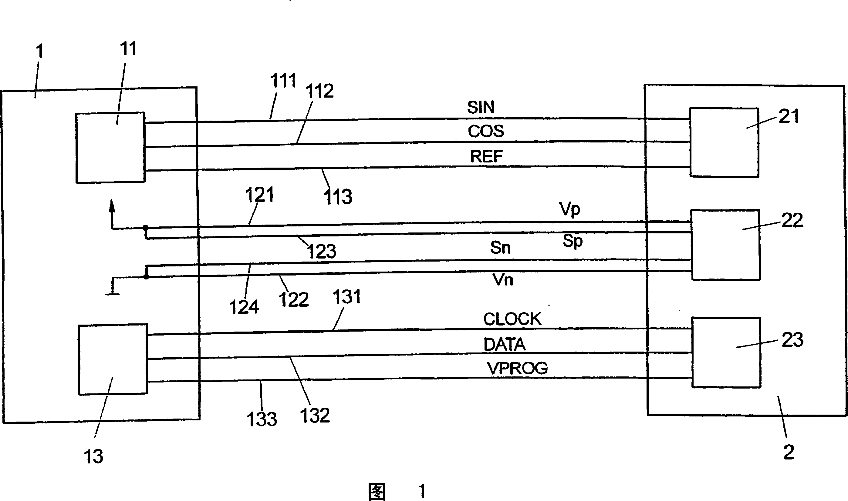
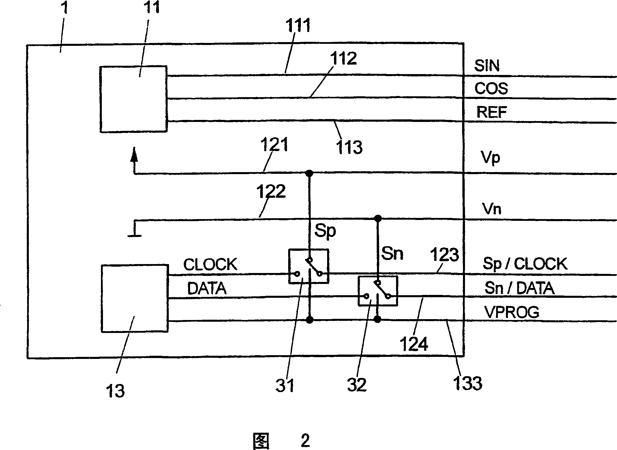
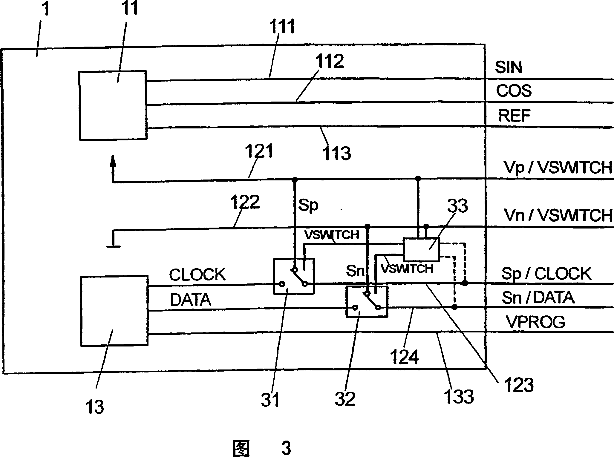
[0033] 1 shows a measurement system 1 known from the prior art, which communicates with the control device via measurement signal lines 111, 112, 113, supply lines 121, 122, serial buses 131, 132 and programming voltage line 133. 2 connections. In this case, the measuring system 1 has a measuring unit for detecting measured values, which are converted into measuring signals SIN, COS, REF and passed in the form of measuring signals SIN, COS, REF via measuring signal lines 111 , 112 , 113 is transmitted to the evaluation unit 21 of the control unit 2 . Furthermore, a configuration unit 13 is arranged in the measuring system 1 , which is used for configuring and calibrating the measuring system 1 and which is connected to the calibration unit 23 of the control unit 2 via serial buses 131 , 132 and a programming voltage line 133 .

[0034] The measuring system 1 can be designed, for example, as a position measuring device for detecting measured values ​​in the form of the positio...


PUM


Abstract

The invention relates to measuring system for measuring at least a measurement value, having at least a sensor line. The sensor line is set to be sensitive line for measuring the state of the measuring system and transmitting the sensor signal indicating the state to the control unit connected to the measuring system. The measuring system has switch unit which switches at least a sensor line of the measuring system. The switching status is dependent on receiving sensor signals so that a data line is provided for transmission of the sensor signals of different data signal.

Description

technical field [0001] The invention relates to a measurement system for detecting at least one measurement signal according to the preamble of claim 1 . Background technique [0002] Such a measuring system has at least one sensor line which, as a sensitive line, detects the state of the system (for example voltage values ​​at the nodes of the circuit board or the supply voltage on the supply line) and sends a sensor signal to the available The control unit connected to the measurement system transmits. The sensor signals transmitted in this way can then be evaluated in the control unit and used to readjust the measuring system, for example the supply voltage supplied to the measuring system for the power supply. A sensor line is thus understood to be a sensitive line in the sense that it is arranged on a component of the system and thus interacts with the component in such a way that it is sensitive to the measuring system or the The states of the components of the measu...

Claims


Application Information

Patent Timeline
IPC IPC(8): G08C19/00G08C19/16G01D5/14H04L12/40
CPCG08C19/00G01D3/022G01D3/08
Inventor A·胡伯
Owner DR JOHANNES HEIDENHAIN GMBH
Why Eureka
Try Eureka