Table with lifting device
A lifting device, table technology, applied in the direction of the table, the table with the height of the table, the legs of general furniture, etc., can solve the problem that the keyboard cannot be raised or lowered, and achieves the improvement of work efficiency, productivity, sustainable development, and security. health effects
- Summary
- Abstract
- Description
- Claims
- Application Information
AI Technical Summary
Problems solved by technology
Method used
Image
Examples
Embodiment 1
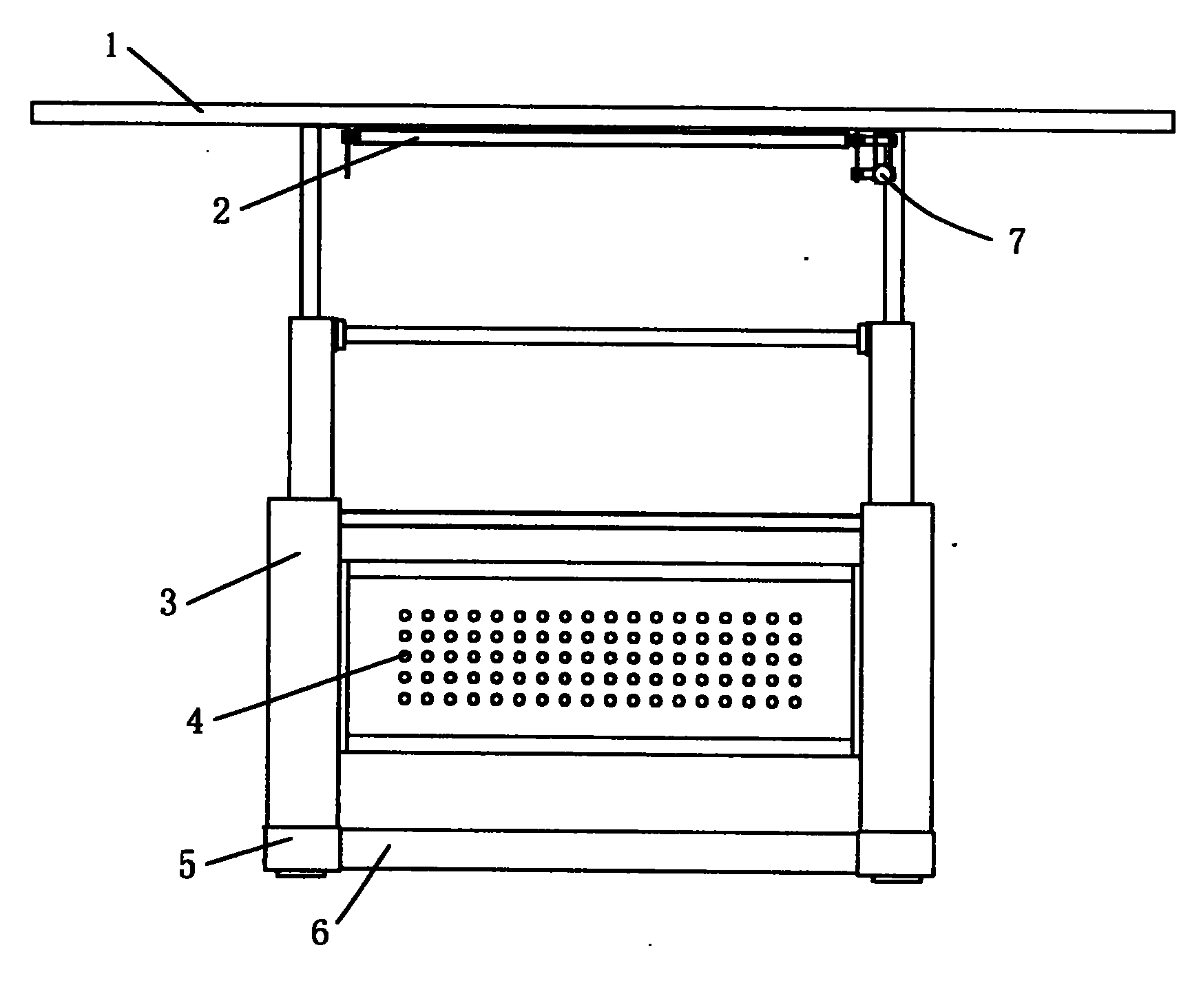
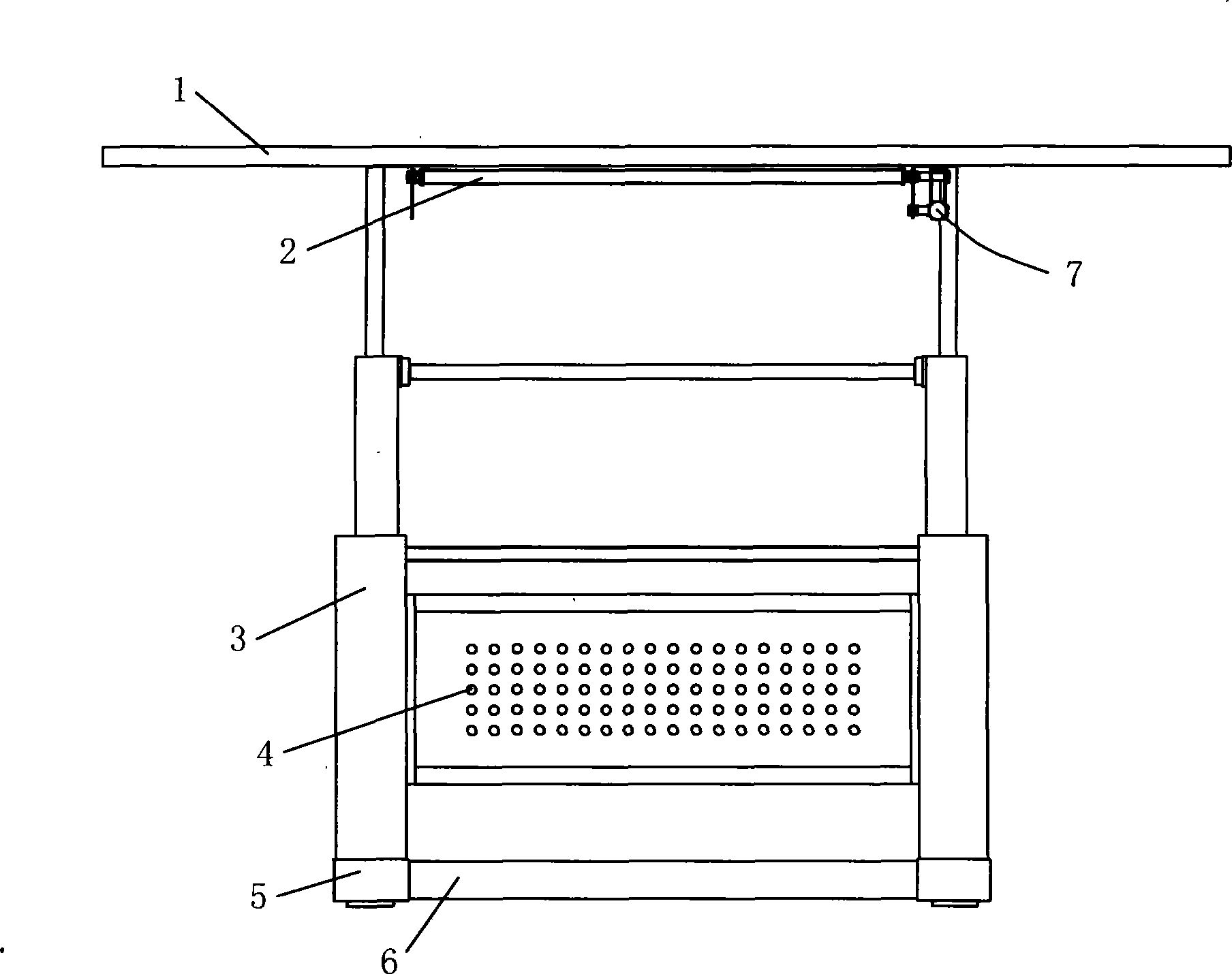
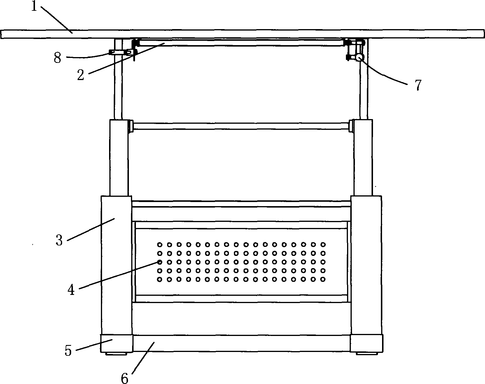
[0053] As shown in Figure 1A. A table with a lifting device includes a desktop 1, a desktop angle adjusting device 2, a lifting device 3, a column cavity connecting plate 4, a column base 5, and a column base connecting plate 6.
[0054] For the first embodiment, it also includes a braking device 328 (which will be described below). A schematic diagram of the desk according to the first embodiment is shown in FIG. 1B, which shows the brake handle 8 of the brake device 328 and the angle adjustment knob 7 of the desk angle adjustment device 2 which will be described below.
[0055] The specific structure of the desktop angle adjusting device 2 is shown in FIG. 2. It includes a hinged fulcrum 21 of a fixed desktop arranged on one side of the desktop, an angle adjusting knob 7 connected with the hinged fulcrum 21 of the fixed desktop, and an angle adjusting knob 7. The transmission screw 24 connected to the handle 7, the transmission screw fixing fulcrum 23 that fixes the transmission...
Embodiment 2
[0066] The main difference between this embodiment and Embodiment 1 lies in the transmission device. The transmission device in this embodiment will be described below with reference to the accompanying drawings.
[0067] See Figure 5. The lifting device in this embodiment includes a lifting mechanism and a transmission mechanism. The lifting mechanism includes a column cavity of a three-stage stack, and the transmission mechanism includes a telescopic three-stage stack corresponding to the column cavity of the three-stage stack. For the threaded push rod, the implementation of the lifting mechanism is the same as that of the first embodiment, and those skilled in the art can refer to the above-mentioned embodiment 1 to implement the corresponding part of the second embodiment, which will not be repeated here. Only the transmission mechanism in the lifting device will be described in detail below.
[0068] The transmission mechanism in the lifting device of this embodiment include...
Embodiment 3
[0075] The difference between this embodiment and Embodiment 1 and Embodiment 2 mainly lies in the transmission mechanism in the lifting device. The implementation of the transmission mechanism of the lifting device in this embodiment will be described below with reference to the accompanying drawings.
[0076] The transmission mechanism of the lifting device in this embodiment includes a traction steel cable 3110, a steel cable lifting bearing pulley 3114, 3214, and a third steel cable fixed end 3312. In this embodiment, the lifting mechanism is a non-closed column cavity with an opening on one side of the three-stage stack.
[0077] See Figure 7. In this embodiment, a traction steel cable 3110 is provided in the lifting device, and a steel cable fixed end 3212 is fixedly installed at the lower end of the inner wall of the third-stage column cavity 33 to move up and down and slide with the third-stage column cavity 33 at the same time; The opening side of the upper end is provide...
PUM
 Abstract
Description
Claims
Application Information
 - R&D
- Intellectual Property
- Life Sciences
- Materials
- Tech Scout
- Unparalleled Data Quality
- Higher Quality Content
- 60% Fewer Hallucinations
Browse by: Latest US Patents, China's latest patents, Technical Efficacy Thesaurus, Application Domain, Technology Topic, Popular Technical Reports.
© 2025 PatSnap. All rights reserved.Legal|Privacy policy|Modern Slavery Act Transparency Statement|Sitemap|About US| Contact US: help@patsnap.com


